Overview
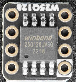
This tutorial builds an STM32 SPI Flash Chip driver from scratch for Winbond’s W25Q-series NOR flash. These chips show up constantly in hobby and embedded projects — on SD-card-shaped modules, on SPI flash breakouts, and soldered directly onto other boards as boot/config storage. Adafruit sells three DIP-breakout versions of this same chip family — the 5632 (W25Q16, 16 Mbit/2 MByte), 5633 (W25Q64, 64 Mbit/8 MByte), and 5634 (W25Q128, 128 Mbit/16 MByte) — identical in pinout, wiring, and logic level, differing only in capacity. This tutorial wires one of these breakouts to a Nucleo-H753ZI over the STM32’s standard SPI peripheral. It builds a small C++ driver class around it: JEDEC ID identification, sector/block/chip erase, and paged read/write. A destructive validation suite proves the driver, and the breadboard wiring, actually work rather than just compile.
This is a companion pair with the QSPI version of this same tutorial, built on identical hardware — the STM32’s dedicated QUADSPI peripheral is a genuinely different implementation, not just “SPI with extra pins,” and the two posts are worth reading together if you’re deciding which mode fits your project.
If you’ve already read STM32 SPI Flash W25Q16JV W25Q64JV External Storage Interface, this post covers similar chip territory but a different scope: that post targets a Nucleo-F446RE and covers the same class of chip as a raw flash driver — it mentions littleFS/FAT as a possible use for this kind of chip, but doesn’t implement one. This post targets the Nucleo-H753ZI, uses the Adafruit breakout boards specifically (including the 128 Mbit capacity), builds a from-scratch validated driver class with a destructive test suite, and is one half of a matched SPI/QSPI pair on identical hardware.
What You Will Learn
- How to wire an Adafruit QSPI DIP flash breakout (W25Q16/W25Q64/W25Q128) to an STM32 Nucleo board for standard single-line SPI operation
- How to write a C++ HAL SPI driver class for JEDEC ID identification, sector/block/chip erase, and paged read/write with automatic page-boundary splitting
- Why this driver manually drives chip-select with a GPIO instead of using SPI1’s hardware NSS output — and why the QSPI version of this same driver does the opposite
- How to bridge CubeMX-generated plain-C
main.cinto a C++ driver class safely, with a null-pointer guard against use-before-init - How to validate flash driver correctness with a destructive test suite — and why a light spot-check (a JEDEC ID read surviving repeated resets) doesn’t actually validate an SPI clock speed the way a full erase/write/read regression pass does
Prerequisites
You should be comfortable creating and building a basic STM32CubeIDE project and have a working knowledge of C and C++. Familiarity with the general shape of an SPI transaction (clock, MOSI, MISO, chip-select) is helpful but not required — this tutorial explains the multi-phase command structure this specific chip requires as it goes. Debug output in this project is redirected to printf over USART1 through an external FTDI USB-to-serial adapter; if you haven’t set this up before, any STM32CubeIDE project generated from the C++ integration post‘s conventions already has it configured.
Materials List
- Nucleo-H753ZI development board
- Adafruit QSPI DIP Flash breakout — any of 5632 (W25Q16), 5633 (W25Q64), or 5634 (W25Q128). All three are pin-identical; this tutorial’s hardware testing used the 5634.
- Breadboard and jumper wires
- FTDI USB-to-serial adapter, for USART1 debug output
- USB cable (Micro-USB or USB-C, depending on your Nucleo board’s ST-LINK connector)
Project Structure
H753_CPP_W25Q_SPI_Flash_Read_Write_01/
├── W25Q/
│   ├── w25q_commands.h
│   ├── W25QFlashSPI.hpp
│   ├── W25QFlashSPI.cpp
│   ├── w25q_validation.hpp
│   └── w25q_validation.cpp
├── Core/
│   ├── Inc/
│   │   ├── main.h
│   │   └── entryPointCPP.hpp
│   └── Src/
│       ├── main.c
│       └── entryPointCPP.cpp
├── Doxyfile
├── H753_CPP_W25Q_SPI_Flash_Read_Write_01.ioc
├── H753_CPP_W25Q_SPI_Flash_Read_Write_01.pdf
├── H753_CPP_W25Q_SPI_Flash_Read_Write_01.txt
├── LICENSE
├── project_mainpage.dox
├── STM32H753ZITX_FLASH.ld
└── STM32H753ZITX_RAM.ld
Hardware Configuration / Pinouts
Overview
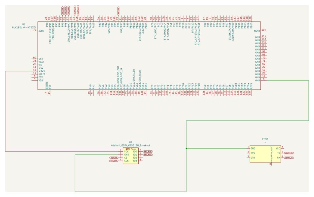
The Adafruit breakout exposes eight pins — 3V, G, CS, IO0, IO1, IO2, IO3, CLK — identical across all three capacity variants. In standard SPI mode, only four of the six logic pins actually carry data: IO0 is MOSI, IO1 is MISO, CLK is the SPI clock, and CS is chip-select. IO2 (Write Protect) and IO3 (Hold) are QSPI-only data lines with no role in single-line SPI mode — tie both to 3.3V so they don’t float.
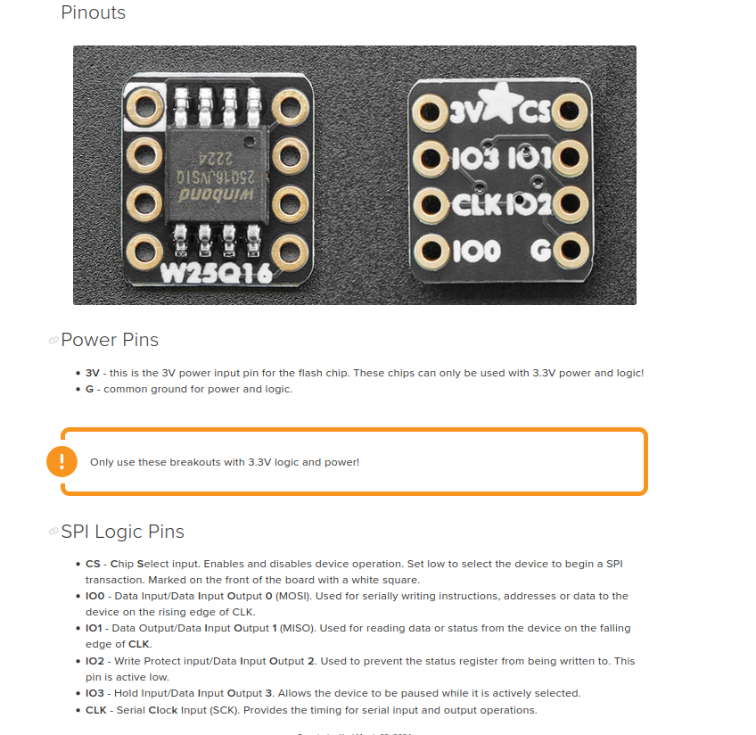
These breakouts are 3.3V logic and power only — the Nucleo-H753ZI’s 3.3V rail and GND are the only power connections needed. Never connect 5V to 3V.
| Breakout Pin | Nucleo-H753ZI Pin | Function |
|---|---|---|
3V | 3V3 | 3.3V power |
G | GND | Ground |
CLK | PA5 | SPI1_SCK |
IO1 | PA6 | SPI1_MISO |
IO0 | PA7 | SPI1_MOSI |
CS | PB6 | GPIO output, labeled WQ25_CS |
IO2 | 3V3 | Write Protect, tied high (unused in SPI mode) |
IO3 | 3V3 | Hold, tied high (unused in SPI mode) |
Debug output uses the standard USART1 setup on this site: PA9 (TX) and PA10 (RX), asynchronous mode, through an external FTDI USB-to-serial adapter rather than the board’s onboard ST-LINK virtual COM port.
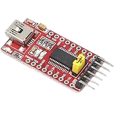
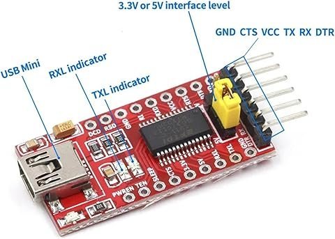
FTDI Pinouts
FTDI to USB Pinout from right to left
- Pin 1 – GND
- Pin 4 – TX
- Pin 5 – RX
- USB Mini – Connect to PC via USB cable
Make sure the jumper is set to 5V — the FTDI board is powered from the USB mini cable, and a computer’s USB port supplies 5V.
Schematic
Why chip-select is a manual GPIO
It would be reasonable to expect SPI1’s own hardware NSS output to drive chip-select here — that’s what it’s for. This driver deliberately doesn’t use it, and the reason matters for understanding both this post and its QSPI companion.
Every meaningful W25Q command is a multi-phase sequence: an opcode byte, then (for most commands) a 3-byte address, then a data phase — and all of it has to happen under one continuous CS-low period, or the chip treats it as multiple unrelated commands instead of one. Generic SPI hardware has no built-in concept of “phases”: each HAL_SPI_Transmit/HAL_SPI_Receive call is an independent transaction as far as the peripheral is concerned. If SPI1’s hardware NSS were driving chip-select, it would deassert CS the instant each individual call finished — aborting the command mid-sequence before the address or data phase ever went out.
Driving WQ25_CS as a plain GPIO output instead lets the driver bracket the whole multi-call sequence itself — assert CS, run every HAL call the command needs, then deassert CS only once the entire sequence is done. This is exactly the pattern in csEnable()/csDisable() below.
This is also precisely where the QSPI version of this tutorial does the opposite, and for a reason worth understanding rather than memorizing: QUADSPI’s command model is not simpler than SPI’s — it’s the identical opcode/address/dummy-cycles/data phase structure under the hood. The difference is that STM32’s QUADSPI peripheral has hardware that natively understands that phase structure, expressed as a single QSPI_CommandTypeDef passed to one HAL_QSPI_Command() call. Because the peripheral itself already knows where one command starts and ends, it can safely own NCS in hardware without the mid-sequence-abort problem SPI1’s NSS would have here. Same electrical requirement (one continuous chip-select period per command), solved by hardware in one case and by software in the other, because only one of the two peripherals actually models the concept of a “phase.”
Pinouts & Configurations
The complete CubeMX pin assignment and peripheral configuration is captured in the IOC report below.
Project Setup
Create a new STM32CubeIDE project targeting the Nucleo-H753ZI board, with C++ enabled (even though main.c itself stays plain C — see the C/C++ bridge section below). In the .ioc pinout view:
- Enable SPI1 in Full-Duplex Master mode. Set NSS to Software — not Hardware NSS Output — per the CS/NSS explanation above.
- Set SPI1’s baud rate prescaler to 16 (12.0 MBit/s at this board’s default clock configuration). See the clock-speed testing story further down — this value is the result of testing, not a default worth trusting blindly.
- Configure PB6 as a GPIO Output, labeled
WQ25_CS, initial level high (deasserted). - Enable USART1 in Asynchronous mode on PA9/PA10 for
printfredirect, per this site’s standard debug UART convention.
Code Walkthrough
This project’s flash driver is written as a C++ class, but CubeMX regenerates main.c as plain C every time the .ioc file changes — putting C++ code directly in main.c would get silently discarded on the next regeneration. The bridge pattern below (from the C++ integration post) solves this: main.c stays plain C and calls a small set of extern "C" functions that wrap the real C++ driver object.
w25q_commands.h — command opcodes and geometry
The Winbond command set and memory geometry constants, shared between this SPI driver and its QSPI counterpart — the opcodes and geometry are identical regardless of which transport carries them. Adapted from the command set documented in Adafruit’s own Adafruit_SPIFlash library (MIT License), which in turn reflects the standard JEDEC-style command set used across essentially all Winbond W25Q parts.
/*
 * w25q_commands.h
 *
 * Winbond W25Q-series SPI/QSPI flash command opcodes and geometry constants.
 * Shared between the SPI and QSPI variants of this driver -- the opcodes and
 * memory geometry are identical regardless of transport.
 *
 * Adapted from the command set documented in Adafruit_SPIFlash's
 * Adafruit_FlashTransport.h (https://github.com/adafruit/Adafruit_SPIFlash,
 * MIT License, Copyright (c) 2019 hathach for Adafruit Industries), which in
 * turn reflects the standard JEDEC-style command set used across essentially
 * all Winbond W25Q parts (confirmed against the W25Q16/W25Q64/W25Q128
 * datasheets used by the Adafruit 5632/5633/5634 breakout boards).
 *
 *  Created on: Aug 30, 2026
 *      Author: johng
 */

#ifndef W25Q_W25Q_COMMANDS_H_
#define W25Q_W25Q_COMMANDS_H_

/** @brief Winbond W25Q command opcodes. */
enum {
  W25Q_CMD_READ = 0x03,               ///< Single-line Read Data
  W25Q_CMD_FAST_READ = 0x0B,          ///< Single-line Fast Read (1 dummy byte)
  W25Q_CMD_QUAD_READ = 0x6B,          ///< 1-line address, 4-line data (QSPI variant only)

  W25Q_CMD_READ_JEDEC_ID = 0x9F,      ///< Manufacturer + memory type + capacity

  W25Q_CMD_PAGE_PROGRAM = 0x02,       ///< Single-line Page Program
  W25Q_CMD_QUAD_PAGE_PROGRAM = 0x32,  ///< 1-line address, 4-line data (QSPI variant only)

  W25Q_CMD_READ_STATUS1 = 0x05,       ///< Status Register 1 (BUSY, WEL, block-protect bits)
  W25Q_CMD_READ_STATUS2 = 0x35,       ///< Status Register 2 (QE and other bits)
  W25Q_CMD_WRITE_STATUS1 = 0x01,
  W25Q_CMD_WRITE_STATUS2 = 0x31,

  W25Q_CMD_WRITE_ENABLE = 0x06,
  W25Q_CMD_WRITE_DISABLE = 0x04,

  W25Q_CMD_ERASE_SECTOR = 0x20,       ///< Erase the 4KB sector containing the given address
  W25Q_CMD_ERASE_BLOCK = 0xD8,        ///< Erase the 64KB block containing the given address
  W25Q_CMD_ERASE_CHIP = 0xC7,

  W25Q_CMD_ENABLE_RESET = 0x66,       ///< Must precede W25Q_CMD_RESET
  W25Q_CMD_RESET = 0x99,
};

/** @brief Memory geometry constants common to the W25Q16/W25Q64/W25Q128 family. */
enum {
  W25Q_PAGE_SIZE = 256,               ///< Max bytes per Page Program command
  W25Q_SECTOR_SIZE = 4 * 1024UL,      ///< Erase granularity for W25Q_CMD_ERASE_SECTOR
  W25Q_BLOCK_SIZE = 64 * 1024UL,      ///< Erase granularity for W25Q_CMD_ERASE_BLOCK
};

/** @brief Winbond's JEDEC manufacturer ID byte, returned first by W25Q_CMD_READ_JEDEC_ID. */
#define W25Q_JEDEC_MANUFACTURER_ID 0xEF

#endif /* W25Q_W25Q_COMMANDS_H_ */W25QFlashSPI.hpp — the driver class declaration
Every public method here returns a plain bool and propagates failure to the caller — with one deliberate exception. Init() calls Error_Handler() directly on a HAL-level communication failure, on the reasoning that a failed SPI transfer on the very first transaction indicates a setup problem (bad wiring, dead chip, wrong pin config) that retrying can’t fix — the same fail-hard behavior CubeMX’s own generated peripheral-init code already uses elsewhere in main.c. A chip that responds but returns the wrong JEDEC ID is a different, non-fatal outcome (wrong or missing chip, not a bus fault) and simply returns false from Init() instead.
Note also the class-level thread-safety warning, and eraseRange()‘s sector-alignment warning — both documented explicitly rather than left as gotchas for a reader to discover the hard way.
/*
 * W25QFlashSPI.hpp
 *
 * STM32 HAL SPI driver for the Winbond W25Q-series QSPI DIP breakout boards
 * (Adafruit 5632/5633/5634 -- W25Q16/W25Q64/W25Q128), operated in standard
 * single-line SPI mode.
 *
 * Adapted from Adafruit_SPIFlash (https://github.com/adafruit/Adafruit_SPIFlash,
 * MIT License, Copyright (c) 2019 hathach for Adafruit Industries) as a design
 * reference for the command set and driver structure -- this is an independent
 * STM32 HAL implementation, not a direct port of Adafruit's Arduino source
 * (which depends on Arduino-only types this toolchain doesn't have).
 *
 *  Created on: Aug 30, 2026
 *      Author: johng
 */

#ifndef W25Q_W25QFLASHSPI_HPP_
#define W25Q_W25QFLASHSPI_HPP_

#include "main.h"
#include "w25q_commands.h"

/**
 * @brief STM32 HAL SPI1 driver for a Winbond W25Q-series flash chip
 *        (Adafruit 5632/5633/5634), operated in standard single-line SPI
 *        mode with software-controlled chip select (WQ25_CS -- see main.h
 *        for the current pin assignment).
 *
 * @warning Not thread-safe or ISR-safe. There is no mutex or reentrancy
 *          guard anywhere in this class. The specific mechanism: several
 *          public methods (writeBuffer(), eraseSector(), waitUntilReady())
 *          are themselves made up of multiple separate csEnable()/
 *          HAL_SPI_.../csDisable() brackets in sequence -- e.g. writeBuffer()
 *          calls writeEnable() (its own CS bracket), then a second CS
 *          bracket for the Page Program command, then waitUntilReady()
 *          (a loop of further CS brackets polling the status register).
 *          Only the inside of each individual bracket is atomic. If a
 *          context switch lands in the gap *between* brackets -- e.g. right
 *          after writeEnable() succeeds but before the Page Program command
 *          is actually sent -- and a second task's call into this same
 *          driver instance runs in that gap, that task's own CS-low period
 *          and command bytes land on the wire interleaved with the first
 *          task's half-finished operation. Both share the same physical
 *          SPI1 peripheral and the same CS pin, so the chip sees a single
 *          corrupted byte stream, not two separate operations -- there is
 *          no way for either task, or the chip, to tell the interleaving
 *          happened. If this driver is reused in a multi-task project, the
 *          caller is responsible for serializing all access (e.g. a mutex
 *          held for the duration of each public method call, not just each
 *          individual CS bracket).
 */
class W25QFlashSPI {
public:
	/**
	 * @brief Constructs the driver.
	 * @param spiTimeoutMs Per-transaction HAL_SPI_Transmit/Receive timeout, in
	 *        milliseconds, used for every SPI transfer this driver issues.
	 *        Distinct from waitUntilReady()'s timeout, which bounds the total
	 *        time spent polling the BUSY bit across many such transactions.
	 *        Defaults to 100ms; pass a different value if a specific
	 *        operation (e.g. a slow bus speed) needs more headroom.
	 */
	explicit W25QFlashSPI(uint32_t spiTimeoutMs = 100);

	/**
	 * @brief Resets the chip and verifies communication via the JEDEC ID.
	 *
	 * Unlike every other public method below, a HAL-level SPI failure here
	 * calls Error_Handler() rather than returning false. A communication
	 * failure on the very first transaction at startup indicates a setup
	 * problem (bad wiring, dead chip, wrong pin config) that retrying can't
	 * fix -- matching how CubeMX's own generated peripheral-init code already
	 * behaves elsewhere in main.c. A *wrong* JEDEC ID (chip present and
	 * responding, just not a W25Q) is not treated as a HAL failure and simply
	 * returns false -- that's a legitimate, non-fatal "wrong/missing chip"
	 * outcome, not a bus fault.
	 * @retval true if a W25Q-family JEDEC manufacturer ID (0xEF) was read back.
	 */
	bool Init();

	/**
	 * @brief Reads the 3-byte JEDEC ID (manufacturer, memory type, capacity).
	 *
	 * Distinguishes a failed SPI transfer from a successful transfer that
	 * simply read back an unexpected ID (wrong/missing chip) -- the return
	 * value reports the former, id's contents (valid only when this returns
	 * true) determine the latter. Not escalated to Error_Handler() -- see the
	 * class-level note on Init() vs. every other method; use Init() itself
	 * for the fail-hard startup check.
	 * @param id Destination for the 24-bit JEDEC ID (manufacturer byte in
	 *           bits [23:16]). Left unmodified if this returns false.
	 * @retval true if the SPI transfer succeeded (regardless of whether id
	 *         turned out to be a genuine W25Q manufacturer ID), false if the
	 *         transfer itself failed -- caller may retry; not escalated to
	 *         Error_Handler() (see Init()).
	 */
	bool readJEDECID(uint32_t &id);

	/**
	 * @brief Reads both status registers.
	 * @param status1 Destination for Status Register 1 (BUSY, WEL, block-protect bits).
	 * @param status2 Destination for Status Register 2 (QE and other bits).
	 * @retval true on success, false if either SPI transfer failed -- caller
	 *         may retry; not escalated to Error_Handler() (see Init()).
	 */
	bool readStatus(uint8_t &status1, uint8_t &status2);

	/**
	 * @brief Polls Status Register 1's BUSY bit until clear or timeout.
	 * @param timeout_ms Maximum time to wait, in milliseconds.
	 * @retval true if the chip became ready before the timeout.
	 */
	bool waitUntilReady(uint32_t timeout_ms = 100);

	/**
	 * @brief Erases the single 4KB sector containing the given address.
	 * @param addr Any address within the sector to erase.
	 * @retval true on success, false if the erase command's SPI transfer
	 *         failed or the BUSY-wait timed out -- not escalated to
	 *         Error_Handler() (see Init()).
	 */
	bool eraseSector(uint32_t addr);

	/**
	 * @brief Erases every sector spanned by [addr, addr + len), computing
	 *        the sector boundaries automatically -- the erase-side
	 *        counterpart to writeBuffer()'s automatic page-splitting.
	 *
	 * Needed for any write larger than one sector (4KB): a caller who only
	 * erases the sector addr starts in, then calls writeBuffer() with a
	 * length that spans into a second sector, gets silently corrupted data
	 * in that second sector -- Page Program can only clear bits, and an
	 * unerased sector still holds whatever was there before. Matching
	 * writeBuffer()'s "any length" contract on the write side without this
	 * on the erase side would leave that exact landmine for the caller to
	 * find the hard way.
	 *
	 * @warning Erase always operates on whole 4KB sectors -- there is no
	 *          finer granularity on this chip. If addr isn't sector-aligned,
	 *          or addr+len doesn't end exactly on a sector boundary, this
	 *          WILL also erase any other data sharing those same sectors,
	 *          even data outside the [addr, len) range you asked for. This
	 *          is true of eraseSector()/eraseBlock() too, but is easier to
	 *          trigger by surprise here since the caller may not be
	 *          thinking in sector-aligned terms at all when picking addr
	 *          and len for a write. If you're storing multiple independent
	 *          pieces of data on this chip, keep each one sector-aligned
	 *          (or give each its own dedicated sector(s)) precisely so an
	 *          erase of one doesn't silently take out another.
	 * @param addr Starting address of the range to erase.
	 * @param len  Length of the range, in bytes.
	 * @retval true on success, false if any sector's erase failed -- not
	 *         escalated to Error_Handler() (see Init()). Sectors already
	 *         erased before a failing one remain erased.
	 */
	bool eraseRange(uint32_t addr, uint32_t len);

	/**
	 * @brief Erases the single 64KB block containing the given address.
	 * @param addr Any address within the block to erase.
	 * @retval true on success, false if the erase command's SPI transfer
	 *         failed or the BUSY-wait timed out -- not escalated to
	 *         Error_Handler() (see Init()).
	 */
	bool eraseBlock(uint32_t addr);

	/**
	 * @brief Erases the entire chip. Can take tens of seconds on larger
	 *        capacities -- verify the timeout against the specific chip's
	 *        datasheet (16/64/128 Mbit erase times differ significantly).
	 * @retval true on success, false if the erase command's SPI transfer
	 *         failed or the BUSY-wait timed out -- not escalated to
	 *         Error_Handler() (see Init()).
	 */
	bool eraseChip();

	/**
	 * @brief Reads len bytes starting at addr into buf.
	 * @param addr Starting flash address to read from.
	 * @param buf  Destination buffer, must be at least len bytes.
	 * @param len  Number of bytes to read.
	 * @retval true on success, false if the SPI transfer failed -- caller
	 *         may retry; not escalated to Error_Handler() (see Init()).
	 */
	bool readBuffer(uint32_t addr, uint8_t *buf, uint32_t len);

	/**
	 * @brief Writes len bytes starting at addr, paging internally at 256-byte
	 *        boundaries as the chip's Page Program command requires.
	 * @param addr Starting flash address to write to. The destination must
	 *             already be erased -- flash bits can only be cleared
	 *             (1 -> 0), never set, outside of an erase operation.
	 * @param data Source buffer of len bytes to write.
	 * @param len  Number of bytes to write.
	 * @retval true on success, false if any page's SPI transfer failed or its
	 *         BUSY-wait timed out -- not escalated to Error_Handler() (see
	 *         Init()). Pages already written before the failing one remain
	 *         written; the caller can inspect/retry from the failure point.
	 */
	bool writeBuffer(uint32_t addr, const uint8_t *data, uint32_t len);

private:
	SPI_HandleTypeDef *_hspi;

	/** @brief Per-transaction HAL_SPI_Transmit/Receive timeout, in milliseconds. See the constructor. */
	uint32_t _spiTimeoutMs;

	/**
	 * @brief Manually asserts chip select via a plain GPIO (WQ25_CS, PA8).
	 *
	 * Deliberately NOT using SPI1's hardware NSS output mode. Every
	 * meaningful W25Q command (Read, Page Program, etc.) is a multi-phase
	 * sequence -- opcode, then address, then data -- that must all happen
	 * under one continuous CS-low period. Generic SPI hardware has no
	 * concept of "phases": each HAL_SPI_Transmit/Receive call is an
	 * independent transaction to the peripheral, so hardware NSS would
	 * deassert CS between calls and abort the command mid-sequence.
	 * Software-controlled CS lets us bracket the whole multi-call sequence
	 * ourselves. (Contrast with the QSPI variant of this driver, where
	 * QUADSPI's hardware-managed NCS is correct rather than a workaround
	 * to avoid -- see W25QFlashQSPI.hpp.)
	 */
	void csEnable();

	/** @brief Deasserts chip select. See csEnable(). */
	void csDisable();

	/**
	 * @brief Issues Write Enable (0x06). Required before any program/erase command.
	 * @retval HAL_OK, or the HAL error/timeout code from the underlying SPI transfer.
	 */
	HAL_StatusTypeDef writeEnable();

	/**
	 * @brief Sends a single-byte command with no response/data, e.g. Write
	 *        Enable, Reset.
	 * @param cmd Command opcode.
	 * @retval HAL_OK, or the HAL error/timeout code from the underlying SPI transfer.
	 */
	HAL_StatusTypeDef runCommand(uint8_t cmd);

	/**
	 * @brief Sends a command opcode, then reads len bytes of response,
	 *        e.g. Read Status, Read JEDEC ID.
	 * @param cmd  Command opcode.
	 * @param resp Destination buffer for the response.
	 * @param len  Number of response bytes to read.
	 * @retval HAL_OK, or the HAL error/timeout code from the underlying SPI transfer.
	 */
	HAL_StatusTypeDef readCommand(uint8_t cmd, uint8_t *resp, uint32_t len);

	/**
	 * @brief Sends a command opcode, then writes len bytes of data,
	 *        e.g. Write Status.
	 * @param cmd  Command opcode.
	 * @param data Data bytes to write following the opcode.
	 * @param len  Number of data bytes.
	 * @retval HAL_OK, or the HAL error/timeout code from the underlying SPI transfer.
	 */
	HAL_StatusTypeDef writeCommand(uint8_t cmd, const uint8_t *data, uint32_t len);

	/**
	 * @brief Sends Write Enable, then a command opcode followed by a 3-byte
	 *        address, e.g. Sector Erase, Block Erase.
	 * @param cmd  Erase command opcode.
	 * @param addr Address identifying the sector/block to erase.
	 * @retval HAL_OK, or the HAL error/timeout code from the underlying SPI transfer.
	 */
	HAL_StatusTypeDef eraseCommand(uint8_t cmd, uint32_t addr);

	/**
	 * @brief Packs a 24-bit address into 3 big-endian bytes as the W25Q
	 *        command protocol requires.
	 * @param buf  Destination, must be at least 3 bytes.
	 * @param addr Address to pack (only the low 24 bits are used).
	 */
	void fillAddress(uint8_t *buf, uint32_t addr);
};

#endif /* W25Q_W25QFLASHSPI_HPP_ */W25QFlashSPI.cpp — the implementation
csEnable()/csDisable() are the manual GPIO chip-select brackets discussed above. Every command method — runCommand(), readCommand(), writeCommand(), eraseCommand() — wraps its HAL calls in exactly one such bracket, keeping each multi-phase command atomic from the chip’s perspective. writeBuffer() automatically splits any write across the chip’s 256-byte page boundaries, and eraseRange() is its erase-side counterpart — computing which whole 4KB sectors a range spans so a write larger than one sector doesn’t silently corrupt whatever un-erased data sits in the next sector.
/*
 * W25QFlashSPI.cpp
 *
 *  Created on: Aug 30, 2026
 *      Author: johng
 */

#include "W25QFlashSPI.hpp"

extern SPI_HandleTypeDef hspi1;

W25QFlashSPI::W25QFlashSPI(uint32_t spiTimeoutMs) : _hspi(&hspi1), _spiTimeoutMs(spiTimeoutMs) {
}

void W25QFlashSPI::csEnable() {
	HAL_GPIO_WritePin(WQ25_CS_GPIO_Port, WQ25_CS_Pin, GPIO_PIN_RESET);
}

void W25QFlashSPI::csDisable() {
	HAL_GPIO_WritePin(WQ25_CS_GPIO_Port, WQ25_CS_Pin, GPIO_PIN_SET);
}

void W25QFlashSPI::fillAddress(uint8_t *buf, uint32_t addr) {
	buf[0] = (uint8_t)(addr >> 16);
	buf[1] = (uint8_t)(addr >> 8);
	buf[2] = (uint8_t)(addr);
}

HAL_StatusTypeDef W25QFlashSPI::runCommand(uint8_t cmd) {
	csEnable();
	HAL_StatusTypeDef status = HAL_SPI_Transmit(_hspi, &cmd, 1, _spiTimeoutMs);
	csDisable();
	return status;
}

HAL_StatusTypeDef W25QFlashSPI::readCommand(uint8_t cmd, uint8_t *resp, uint32_t len) {
	csEnable();
	HAL_StatusTypeDef status = HAL_SPI_Transmit(_hspi, &cmd, 1, _spiTimeoutMs);
	if (status == HAL_OK && len > 0) {
		status = HAL_SPI_Receive(_hspi, resp, len, _spiTimeoutMs);
	}
	csDisable();
	return status;
}

HAL_StatusTypeDef W25QFlashSPI::writeCommand(uint8_t cmd, const uint8_t *data, uint32_t len) {
	csEnable();
	HAL_StatusTypeDef status = HAL_SPI_Transmit(_hspi, &cmd, 1, _spiTimeoutMs);
	if (status == HAL_OK && len > 0) {
		status = HAL_SPI_Transmit(_hspi, const_cast<uint8_t *>(data), len, _spiTimeoutMs);
	}
	csDisable();
	return status;
}

HAL_StatusTypeDef W25QFlashSPI::eraseCommand(uint8_t cmd, uint32_t addr) {
	HAL_StatusTypeDef status = writeEnable();
	if (status != HAL_OK) {
		return status;
	}

	uint8_t header[4];
	header[0] = cmd;
	fillAddress(&header[1], addr);

	csEnable();
	status = HAL_SPI_Transmit(_hspi, header, sizeof(header), _spiTimeoutMs);
	csDisable();
	return status;
}

HAL_StatusTypeDef W25QFlashSPI::writeEnable() {
	HAL_StatusTypeDef status = runCommand(W25Q_CMD_WRITE_ENABLE);
	return status;
}

bool W25QFlashSPI::Init() {
	// Fail-hard: see the class-level Doxygen note on Init() for why a HAL
	// failure here calls Error_Handler() while every other method below
	// propagates instead.
	HAL_StatusTypeDef status = runCommand(W25Q_CMD_ENABLE_RESET);
	if (status != HAL_OK) {
		Error_Handler();
	}

	status = runCommand(W25Q_CMD_RESET);
	if (status != HAL_OK) {
		Error_Handler();
	}

	HAL_Delay(1); // tRST: chip reset recovery time

	uint32_t id = 0;
	if (!readJEDECID(id)) {
		Error_Handler(); // SPI transfer itself failed -- distinct from a merely wrong id below
	}

	bool detected = ((id >> 16) & 0xFF) == W25Q_JEDEC_MANUFACTURER_ID;
	return detected; // a *wrong* ID is a legitimate non-fatal outcome, not a HAL fault
}

bool W25QFlashSPI::readJEDECID(uint32_t &id) {
	// Not escalated to Error_Handler() here -- this is a caller-facing
	// method, not Init() itself (which calls this and escalates on our
	// behalf). The bool return lets the caller tell "SPI transfer failed"
	// apart from "transfer succeeded, id just isn't a valid W25Q ID".
	uint8_t resp[3] = { 0, 0, 0 };
	HAL_StatusTypeDef status = readCommand(W25Q_CMD_READ_JEDEC_ID, resp, sizeof(resp));
	if (status != HAL_OK) {
		return false;
	}

	id = ((uint32_t)resp[0] << 16) | ((uint32_t)resp[1] << 8) | resp[2];
	return true;
}

bool W25QFlashSPI::readStatus(uint8_t &status1, uint8_t &status2) {
	HAL_StatusTypeDef status = readCommand(W25Q_CMD_READ_STATUS1, &status1, 1);
	if (status != HAL_OK) {
		return false;
	}

	status = readCommand(W25Q_CMD_READ_STATUS2, &status2, 1);
	if (status != HAL_OK) {
		return false;
	}

	return true;
}

bool W25QFlashSPI::waitUntilReady(uint32_t timeout_ms) {
	uint32_t start = HAL_GetTick();
	uint8_t chipStatus = 0;

	do {
		HAL_StatusTypeDef status = readCommand(W25Q_CMD_READ_STATUS1, &chipStatus, 1);
		if (status != HAL_OK) {
			return false; // SPI transfer failure -- propagate, don't escalate (see Init())
		}

		if ((chipStatus & 0x01) == 0) { // BUSY bit clear
			return true;
		}
	} while ((HAL_GetTick() - start) < timeout_ms);

	return false; // BUSY-bit timeout -- an expected outcome on a long erase,
	              // not a HAL communication failure either way.
}

bool W25QFlashSPI::eraseSector(uint32_t addr) {
	HAL_StatusTypeDef status = eraseCommand(W25Q_CMD_ERASE_SECTOR, addr);
	if (status != HAL_OK) {
		return false;
	}

	bool ready = waitUntilReady(500); // datasheet typical/max sector erase time varies by capacity
	return ready;
}

bool W25QFlashSPI::eraseRange(uint32_t addr, uint32_t len) {
	if (len == 0) {
		return true;
	}

	uint32_t firstSector = addr / W25Q_SECTOR_SIZE;
	uint32_t lastSector = (addr + len - 1) / W25Q_SECTOR_SIZE;

	for (uint32_t sector = firstSector; sector <= lastSector; sector++) {
		if (!eraseSector(sector * W25Q_SECTOR_SIZE)) {
			return false;
		}
	}

	return true;
}

bool W25QFlashSPI::eraseBlock(uint32_t addr) {
	HAL_StatusTypeDef status = eraseCommand(W25Q_CMD_ERASE_BLOCK, addr);
	if (status != HAL_OK) {
		return false;
	}

	bool ready = waitUntilReady(3000); // datasheet typical/max block erase time varies by capacity
	return ready;
}

bool W25QFlashSPI::eraseChip() {
	HAL_StatusTypeDef status = writeEnable();
	if (status != HAL_OK) {
		return false;
	}

	status = runCommand(W25Q_CMD_ERASE_CHIP);
	if (status != HAL_OK) {
		return false;
	}

	// Chip erase time scales heavily with capacity (16/64/128 Mbit) -- verify
	// this timeout against the specific chip's datasheet before relying on it.
	bool ready = waitUntilReady(100000);
	return ready;
}

bool W25QFlashSPI::readBuffer(uint32_t addr, uint8_t *buf, uint32_t len) {
	uint8_t header[4];
	header[0] = W25Q_CMD_READ;
	fillAddress(&header[1], addr);

	csEnable();
	HAL_StatusTypeDef status = HAL_SPI_Transmit(_hspi, header, sizeof(header), _spiTimeoutMs);
	if (status == HAL_OK) {
		status = HAL_SPI_Receive(_hspi, buf, len, _spiTimeoutMs);
	}
	csDisable();

	return status == HAL_OK;
}

bool W25QFlashSPI::writeBuffer(uint32_t addr, const uint8_t *data, uint32_t len) {
	uint32_t written = 0;

	while (written < len) {
		uint32_t pageOffset = (addr + written) % W25Q_PAGE_SIZE;
		uint32_t chunk = W25Q_PAGE_SIZE - pageOffset;
		if (chunk > (len - written)) {
			chunk = len - written;
		}

		HAL_StatusTypeDef status = writeEnable();
		if (status != HAL_OK) {
			return false;
		}

		uint8_t header[4];
		header[0] = W25Q_CMD_PAGE_PROGRAM;
		fillAddress(&header[1], addr + written);

		csEnable();
		status = HAL_SPI_Transmit(_hspi, header, sizeof(header), _spiTimeoutMs);
		if (status == HAL_OK) {
			status = HAL_SPI_Transmit(_hspi, const_cast<uint8_t *>(data + written), chunk, _spiTimeoutMs);
		}
		csDisable();

		if (status != HAL_OK) {
			return false;
		}
		if (!waitUntilReady(50)) { // page program typical max is a few ms; generous margin
			return false;
		}

		written += chunk;
	}

	return true;
}entryPointCPP.hpp / entryPointCPP.cpp — the C/C++ bridge
The driver object is constructed inside initW25QFlash(), called from main() deliberately after HAL_Init()/MX_GPIO_Init()/MX_SPI1_Init() have already run — not as a global static C++ object, which would construct too early. C++ global constructors run inside __libc_init_array() before main() even starts, before any peripheral exists to construct against.
Every bridge function checks w25qFlash == nullptr || !w25qReady before touching the driver object, guarding against a call made before initW25QFlash() has run (or after a failed Init()). Without this guard, calling any of these functions too early would dereference a null pointer and hard-fault — a worse failure mode for a flash driver than, say, an LED simply not blinking.
/*
 * entryPointCPP.hpp
 *
 * C-callable entry points bridging CubeMX-generated main.c (plain C, subject
 * to regeneration whenever the .ioc changes) into the C++ W25QFlashSPI driver.
 *
 * extern "C" here prevents C++ name mangling on these declarations, so
 * main.c can call them directly by name. The driver object itself is
 * constructed inside initW25QFlash(), deliberately called from main() after
 * HAL_Init()/MX_GPIO_Init()/MX_SPI1_Init() have already run -- not as a
 * global static C++ object, which would construct too early (C++ global
 * constructors run in __libc_init_array() before main() even starts, before
 * any peripheral is configured).
 *
 *  Created on: Aug 30, 2026
 *      Author: johng
 */

#ifndef INC_ENTRYPOINTCPP_HPP_
#define INC_ENTRYPOINTCPP_HPP_

#include "main.h"
#include "stdbool.h"

#ifdef __cplusplus
extern "C" {
#endif

/**
 * @brief Constructs the W25QFlashSPI driver and verifies communication with
 *        the chip. Must be called after MX_SPI1_Init() (and therefore after
 *        HAL_Init()/SystemClock_Config()) so the SPI peripheral and CS GPIO
 *        are already configured before the driver touches them.
 * @retval None -- check w25qIsReady() to see whether verification succeeded.
 */
void initW25QFlash(void);

/**
 * @brief Reports whether initW25QFlash() has run and successfully verified
 *        the chip's JEDEC ID. Every other w25q* function below returns false
 *        without touching hardware if this is false, guarding against a call
 *        made before initW25QFlash() (or after a failed begin()).
 * @retval true if the driver is constructed and ready for use.
 */
bool w25qIsReady(void);

/**
 * @brief Reads len bytes starting at addr into buf.
 * @param addr Starting flash address to read from.
 * @param buf  Destination buffer, must be at least len bytes.
 * @param len  Number of bytes to read.
 * @retval true on success, false if not ready or on SPI error.
 */
bool w25qReadBuffer(uint32_t addr, uint8_t *buf, uint32_t len);

/**
 * @brief Writes len bytes starting at addr, paging internally at 256-byte
 *        boundaries. The destination must already be erased.
 * @param addr Starting flash address to write to.
 * @param data Source buffer of len bytes to write.
 * @param len  Number of bytes to write.
 * @retval true on success, false if not ready or on SPI error.
 */
bool w25qWriteBuffer(uint32_t addr, const uint8_t *data, uint32_t len);

/**
 * @brief Erases the 4KB sector containing addr.
 * @param addr Any address within the sector to erase.
 * @retval true on success, false if not ready or on SPI error.
 */
bool w25qEraseSector(uint32_t addr);

/**
 * @brief Reads the 3-byte JEDEC ID (manufacturer, memory type, capacity).
 * @param id Destination for the 24-bit JEDEC ID (manufacturer byte in bits
 *           [23:16]). Left unmodified if this returns false.
 * @retval true on success, false if not ready or the SPI transfer failed.
 */
bool w25qReadJEDECID(uint32_t *id);

/**
 * @brief Runs the destructive W25QValidation test suite and prints results.
 *
 * Overwrites the first sector (W25Q_SECTOR_SIZE bytes) starting at
 * W25Q_VALIDATION_BASE_ADDR. See W25Q_VALIDATION_TEST_ENABLE in main.c --
 * this is meant to be called instead of the normal demo path, not alongside
 * it, and only when destroying that sector's contents is acceptable.
 * @retval None. Prints "flash not initialized" and returns immediately if
 *         initW25QFlash() hasn't succeeded yet.
 */
void w25qRunValidation(void);

#ifdef __cplusplus
}
#endif

#endif /* INC_ENTRYPOINTCPP_HPP_ */
/*
* entryPointCPP.cpp
*
* Created on: Aug 30, 2026
* Author: johng
*/
#include "entryPointCPP.hpp"
#include "W25QFlashSPI.hpp"
#include "w25q_validation.hpp"
#include <stdio.h>
/** @brief The single W25QFlashSPI driver instance, constructed in initW25QFlash(). */
static W25QFlashSPI *w25qFlash = nullptr;
/** @brief Set once begin() succeeds; guards every bridge function below against use-before-init. */
static bool w25qReady = false;
void initW25QFlash(void) {
w25qFlash = new W25QFlashSPI();
w25qReady = w25qFlash->Init();
}
bool w25qIsReady(void) {
return w25qReady;
}
bool w25qReadBuffer(uint32_t addr, uint8_t *buf, uint32_t len) {
if (w25qFlash == nullptr || !w25qReady) {
return false;
}
bool value = w25qFlash->readBuffer(addr, buf, len);
return value;
}
bool w25qWriteBuffer(uint32_t addr, const uint8_t *data, uint32_t len) {
if (w25qFlash == nullptr || !w25qReady) {
return false;
}
bool value = w25qFlash->writeBuffer(addr, data, len);
return value;
}
bool w25qEraseSector(uint32_t addr) {
if (w25qFlash == nullptr || !w25qReady) {
return false;
}
bool value = w25qFlash->eraseSector(addr);
return value;
}
bool w25qReadJEDECID(uint32_t *id) {
if (w25qFlash == nullptr || !w25qReady) {
return false;
}
bool value = w25qFlash->readJEDECID(*id);
return value;
}
void w25qRunValidation(void) {
if (w25qFlash == nullptr || !w25qReady) {
printf("W25Q validation skipped -- flash not initialized\r\n");
return;
}
W25QValidation validation(*w25qFlash);
validation.RunAll();
}main.c — the STM32 SPI Flash Chip demo
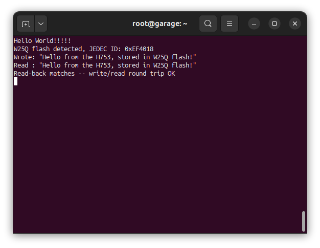
After the standard CubeMX-generated peripheral init, the demo path reads the JEDEC ID (proving communication with the chip), then does the thing this tutorial is actually about: erase a sector, write a short message into it, read it back, and confirm the bytes round-tripped correctly — not just an identify-and-stop check.
int main(void)
{

  /* USER CODE BEGIN 1 */

  /* USER CODE END 1 */

  /* MCU Configuration--------------------------------------------------------*/

  /* Reset of all peripherals, Initializes the Flash interface and the Systick. */
  HAL_Init();

  /* USER CODE BEGIN Init */

  /* USER CODE END Init */

  /* Configure the system clock */
  SystemClock_Config();

  /* USER CODE BEGIN SysInit */

  /* USER CODE END SysInit */

  /* Initialize all configured peripherals */
  MX_GPIO_Init();
  MX_USART1_UART_Init();
  MX_SPI1_Init();
  /* USER CODE BEGIN 2 */

  printf("\x1b[2J\x1b[H");	// Clear the dumb terminal screen
  printf("Hello World!!!!!\r\n");
  fflush(stdout);


  initW25QFlash();
  if (w25qIsReady()) {
#ifdef W25Q_VALIDATION_TEST_ENABLE
	  w25qRunValidation();
#else
	  uint32_t jedecId = 0;
	  if (w25qReadJEDECID(&jedecId)) {
		  printf("W25Q flash detected, JEDEC ID: 0x%06lX\r\n", (unsigned long)jedecId);
	  } else {
		  printf("W25Q flash SPI read failed after Init() succeeded -- check for a loose connection\r\n");
	  }

	  // Demo: erase a sector, write a short message, read it back, and
	  // confirm it round-tripped -- the actual read/write this tutorial is
	  // about, as opposed to the identify-only JEDEC ID check above.
	  const uint32_t demoAddr = 0x000000;
	  const char demoMessage[] = "Hello from the H753, stored in W25Q flash!";

	  if (!w25qEraseSector(demoAddr)) {
		  printf("Demo erase failed\r\n");
	  } else if (!w25qWriteBuffer(demoAddr, (const uint8_t *)demoMessage, sizeof(demoMessage))) {
		  printf("Demo write failed\r\n");
	  } else {
		  uint8_t readBack[sizeof(demoMessage)] = { 0 };
		  if (!w25qReadBuffer(demoAddr, readBack, sizeof(readBack))) {
			  printf("Demo read failed\r\n");
		  } else {
			  printf("Wrote: \"%s\"\r\n", demoMessage);
			  printf("Read : \"%s\"\r\n", readBack);
			  if (memcmp(demoMessage, readBack, sizeof(demoMessage)) == 0) {
				  printf("Read-back matches -- write/read round trip OK\r\n");
			  } else {
				  printf("Read-back MISMATCH\r\n");
			  }
		  }
	  }
#endif
  } else {
	  printf("W25Q flash NOT detected -- check wiring\r\n");
  }

  /* USER CODE END 2 */

  /* Infinite loop */
  /* USER CODE BEGIN WHILE */
  while (1)
  {
    /* USER CODE END WHILE */

    /* USER CODE BEGIN 3 */
  }
  /* USER CODE END 3 */
}Validating the driver
Alongside the normal demo path, this project includes a destructive W25QValidation suite (enabled via W25Q_VALIDATION_TEST_ENABLE in main.c — it overwrites the first sector, so it’s kept separate from the normal demo path) covering four tests: an erased-state check (every byte reads 0xFF after erase), a small read/write round trip, a 20-pattern stuck-at/bit-coupling sweep, and a page-boundary test exercising writeBuffer()‘s internal page-splitting. One representative test:
bool W25QValidation::runErasedStateTest() {
	_report.testsRun++;
	_report.failedTest = W25Q_VALIDATION_TEST_ERASED_STATE;
	_report.failedPhase = W25Q_VALIDATION_PHASE_ERASE;

	printf("[TEST 1] %s\r\n", getTestName(W25Q_VALIDATION_TEST_ERASED_STATE));

	bool erased = _flash.eraseSector(W25Q_VALIDATION_BASE_ADDR);
	if (!erased) {
		recordFailure(W25Q_VALIDATION_TEST_ERASED_STATE, W25Q_VALIDATION_PHASE_ERASE,
				W25Q_VALIDATION_BASE_ADDR, 0xFF, 0x00);
		printFailure();
		return false;
	}

	_report.failedPhase = W25Q_VALIDATION_PHASE_VERIFY;

	uint8_t buf[W25Q_VALIDATION_SMALL_RANGE_SIZE];
	bool readOk = _flash.readBuffer(W25Q_VALIDATION_BASE_ADDR, buf, sizeof(buf));
	if (!readOk) {
		recordFailure(W25Q_VALIDATION_TEST_ERASED_STATE, W25Q_VALIDATION_PHASE_VERIFY,
				W25Q_VALIDATION_BASE_ADDR, 0xFF, 0x00);
		printFailure();
		return false;
	}

	for (uint32_t offset = 0; offset < sizeof(buf); offset++) {
		if (buf[offset] != 0xFF) {
			recordFailure(W25Q_VALIDATION_TEST_ERASED_STATE, W25Q_VALIDATION_PHASE_VERIFY,
					W25Q_VALIDATION_BASE_ADDR + offset, 0xFF, buf[offset]);
			printFailure();
			return false;
		}
	}

printf(" PASS\r\n");This suite is also the reason the SPI clock ended up at 12.0 MBit/s (prescaler 16), not a faster “default” value — and the story behind that number is worth walking through, because it’s a useful lesson beyond just this one project:
- CubeMX’s default prescaler (96 MBit/s) produced an immediate
HAL_ERRORon the very first transfer — correctly caught byInit()‘s fail-hard design. - Dropping to a conservative 3 MBit/s worked immediately, with the first successful JEDEC ID readback:
0xEF4018— Winbond’s manufacturer ID, the standard W25Q family code, and the 128 Mbit capacity byte, confirming the board on hand was the Adafruit 5634. - 12.0 MBit/s (prescaler 16) appeared to work reliably at first.
- Pushing faster than that produced intermittent failures — sometimes working, sometimes not. That’s the classic signature of marginal breadboard signal integrity, not a driver bug, and worth calling out explicitly: an intermittent fault is arguably worse than a consistently slower rate, since a reader hitting occasional garbled reads would more likely suspect their own code than their wiring.
- 24.0 MBit/s (prescaler 8), retested specifically with multiple resets and full power cycles rather than a single run, held clean every time on the JEDEC ID read. At that point it looked validated — but it wasn’t.
- Running the full
W25QValidationsuite at 24 MBit/s failed Test 1 (the erased-state test):eraseSector()and the followingreadBuffer()both reported success, but the read-back byte was0x00, not the erased-state0xFF. The short JEDEC ID read never exercised a real erase-plus-256-byte-read sequence, so it never caught this. - Dropping back to 12.0 MBit/s, the full suite passed cleanly — all four tests, including all 20 patterns and the page-boundary test:
[TEST 1] Erased-state test              PASS
[TEST 2] Small range read/write test    PASS
[TEST 3] Pattern data test (20/20)      PASS
[TEST 4] Page-boundary write test       PASS
W25Q validation complete: PASS
The lesson: repeated resets and power cycles of a light operation — a short ID read — don’t validate a clock speed the way a full read/write/erase regression pass does. A marginal speed can survive dozens of short spot-checks and still fail the first time it’s asked to do a longer, real operation. Test with the actual operation you care about, not a proxy for it.
Real hardware output
Terminal output from the demo path above, running on an actual Nucleo-H753ZI wired to the Adafruit 5634 breakout:
Documentation
This project includes Doxygen-generated documentation built from the inline comments throughout the flash driver, the validation suite, and the C/C++ bridge layer — including the thread-safety warnings and the sector-alignment gotcha called out in the code above.
The documentation is available as a separate download in the Project Downloads section below. Once downloaded, view it locally by opening:
docs/html/index.htmlin a web browser.
Project Downloads
The complete project source code used in this tutorial is available for download, along with the browsable Doxygen documentation. The IOC configuration is available above in the Pinouts & Configurations section — regenerate the CubeMX project from it, then drop in the source below.
- Flash Driver (W25Q/W25QFlashSPI.cpp / .hpp, w25q_commands.h)
- Validation Suite (W25Q/w25q_validation.cpp / .hpp)
- Application Source (main.c / main.h, entryPointCPP.cpp / .hpp)
- Linker Scripts (STM32H753ZITX_FLASH.ld / STM32H753ZITX_RAM.ld)
Browsable Doxygen documentation for the flash driver, the validation suite, and the C/C++ bridge layer:
If you have questions or run into trouble getting the boards programmed and talking to each other, post in the Tutorial Support forum and I will work through it with you. If project source is not linked in the tutorial, it may be available on request — use the email contact option in the site footer.