Overview
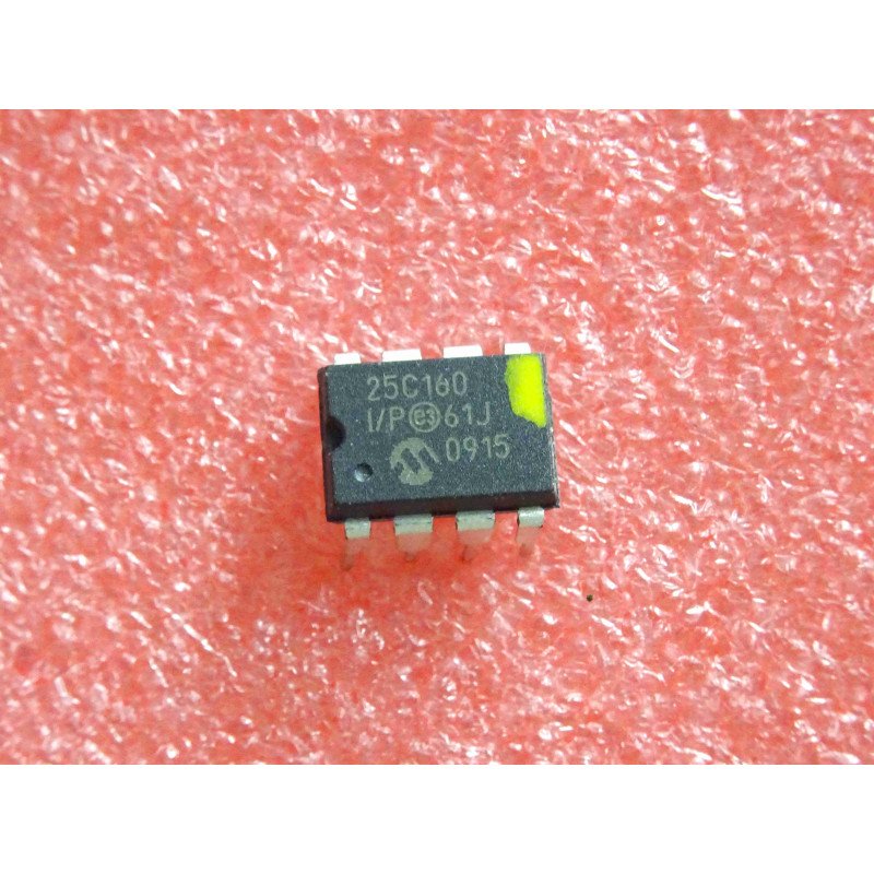
This STM32 I2C MPL3115A2 tutorial shows how to read barometric pressure and temperature from an NXP MPL3115A2 pressure sensor on a NUCLEO-F439ZI (STM32F439ZIT6), and print the converted values to a serial terminal. The firmware initializes the sensor in active barometer mode, polls its data-ready status bits, and takes a new reading roughly every five seconds — printing the temperature in Fahrenheit and the pressure in inches of mercury (inHg) over USART1. Startup includes a manual I2C bus-recovery step that clocks SCL to release a stuck slave if the sensor doesn’t acknowledge on the first probe.
What You Will Learn
- How the MPL3115A2 reports pressure and temperature over I2C, and how to read its STATUS register data-ready bits
- Initializing the sensor: WHO_AM_I verification, standby mode, and enabling the data-ready event flags before entering active barometer mode
- Converting the sensor’s raw Q8.4 temperature and Q18.2 pressure register values into Celsius/Fahrenheit and inches of mercury
- Recovering a stuck I2C bus by manually clocking SCL before reinitializing the peripheral
- Retargeting
printfover USART1 to trace sensor readings on a serial terminal
Prerequisites
This tutorial assumes you can create and build a project in STM32CubeIDE, configure I2C and USART peripherals from CubeMX, and flash a NUCLEO board. You should be comfortable opening a serial terminal at 19200 baud to view the debug output. No prior I2C sensor experience is required — the register-level detail is covered in the Code Walkthrough.
Materials List
- NUCLEO-F439ZI development board (STM32F439ZIT6, onboard ST-Link — no separate programmer needed)
- MPL3115A2 breakout board (I2C, 7-bit address 0x60)
- USB-to-UART adapter (e.g. CP2102 or FTDI) for the serial debug output
- Jumper wires
MPL3115A2 Breakout Board Diagram
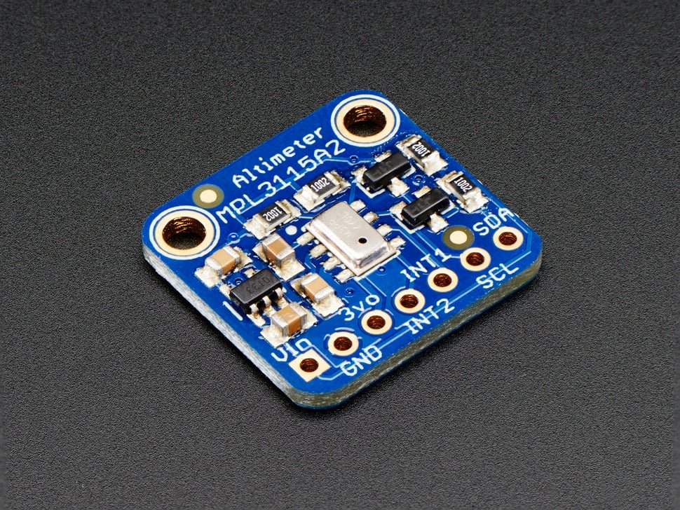
No standalone board datasheet exists for this breakout. Adafruit publishes the actual board schematic and layout as Eagle CAD source files on GitHub — see the Schematic in the Hardware Configuration section below for the board-specific wiring derived from it.
Board Diagram
Project Structure
./F439_CPP_MPL3115A2_Project_01
├── Core
│   ├── Inc
│   │   └── main.h
│   └── Src
│       └── main.c
├── MPL3115A2
│   ├── mpl3115a2.c
│   └── mpl3115a2.h
├── LICENSE
├── README.md
├── STM32F439ZITX_FLASH.ld
└── STM32F439ZITX_RAM.ld
Hardware Configuration / Pinouts
Overview
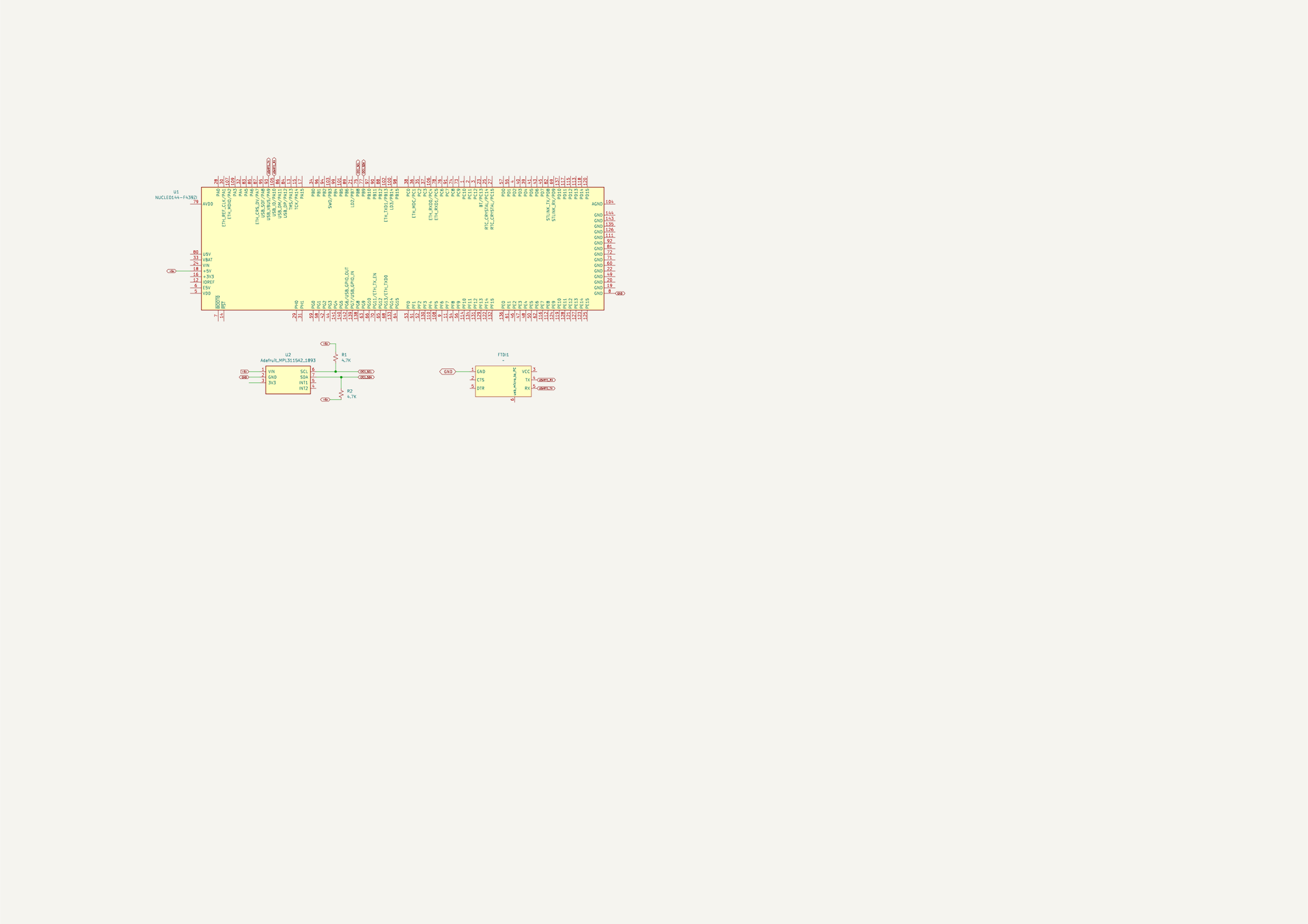
The MPL3115A2 communicates over I2C1 at its fixed 7-bit address 0x60. Only two signal lines are needed — SCL and SDA — plus power and a shared ground with the STM32. A separate USB-to-UART adapter connects to USART1 for the debug trace, since the NUCLEO board’s onboard ST-Link virtual COM port isn’t used for this output.
I2C is open-drain, so SCL and SDA both need pull-up resistors to 3V3. The STM32 side is configured with GPIO_NOPULL, so it isn’t providing them internally — but Adafruit’s MPL3115A2 breakout doesn’t need external ones either: per its published schematic, it has an onboard bidirectional MOSFET level-shifter with 10kΩ pull-ups on both the 3.3V and 5V sides, so the board works correctly at either bus voltage without any extra components.
This tutorial uses a custom STM32 HAL driver rather than an Arduino library. For a reference implementation and register-level details, see Adafruit’s Arduino library for the MPL3115A2.
On startup, if the sensor doesn’t acknowledge the first I2C probe, reset_I2C() temporarily reconfigures PB8 (I2C1_SCL) as an open-drain GPIO and manually toggles it several times before reinitializing I2C1 — a standard bus-recovery technique for releasing an I2C slave that’s stuck holding the bus.
| Signal | STM32F439 pin | Configuration | Connects to |
|---|---|---|---|
| MPL3115A2 SCL | PB8 | I2C1_SCL, standard mode, 100 kHz | SCL on MPL3115A2 |
| MPL3115A2 SDA | PB9 | I2C1_SDA, standard mode, 100 kHz | SDA on MPL3115A2 |
| USART1_TX | PA9 | Asynchronous, 19200 baud | RX of USB-UART adapter |
| USART1_RX | PA10 | Asynchronous, 19200 baud | TX of USB-UART adapter |
The system clock runs at 180 MHz, generated from the internal 16 MHz HSI oscillator through the PLL with the power regulator’s Over-Drive mode enabled — CubeMX configures this automatically when the SYSCLK target is set to 180 MHz on an F439.
FTDI Pinouts
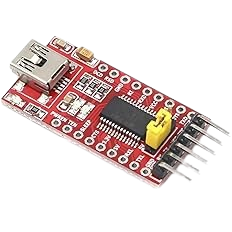
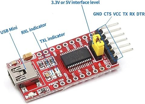
FTDI to USB Pinout from right to left
- Pin 1 – GND
- Pin 4 – TX
- Pin 5 – RX
- USB Mini – Connect to PC via USB cable
Make sure the jumper is set to 5V — the FTDI board is powered from the USB mini cable, and a computer’s USB port supplies 5V.
Schematic
Pinouts & Configurations
The complete CubeMX pin assignment and peripheral configuration is captured in the IOC report below.
Project Setup
Create a new STM32 project in STM32CubeIDE targeting the STM32F439ZITx (or start from the NUCLEO-F439ZI board selector), then configure the peripherals as follows before generating code:
- Clock: set the RCC oscillator to HSI with the PLL enabled (PLLM=8, PLLN=180, PLLP=/2), and enable the power regulator’s Over-Drive mode. This yields a 180 MHz SYSCLK.
- I2C1: enable I2C mode on PB8/PB9, standard mode, 100 kHz clock speed, 7-bit addressing.
- USART1: set the mode to Asynchronous at 19200 baud, 8N1. This puts TX on PA9 and RX on PA10 for the debug trace.
- Generate the project, then copy the
MPL3115A2/driver folder into the project and add it to the include paths and source locations. - In
main.h, defineREDIRECT_PRINTFsoprintf()output is retargeted to USART1. - Call
MPL3115A2_Init(&hi2c1, MPL3115A2_ADDRESS)once after peripheral initialization, then add the polling loop described below.
Code Walkthrough
All of the application logic lives in main.c and the MPL3115A2/ driver, between the CubeMX-generated initialization blocks. We’ll walk through I2C bus recovery, sensor initialization, the status-polling and register-read functions, printf retargeting, and finally the main loop that ties it together.
Recovering a stuck I2C bus
If the sensor doesn’t acknowledge on the first I2C probe, reset_I2C() steps in before MPL3115A2_Init() retries. It temporarily reconfigures PB8 as an open-drain GPIO output, pulls it low, then toggles it high and low ten times with a 20 ms delay between edges — manually clocking SCL to give a slave that’s stuck holding the bus a chance to release it — before reinitializing I2C1 through the CubeMX-generated MX_I2C1_Init().
/**
  * @brief Recover the I2C1 bus by manually clocking SCL before reinitialization.
  *
  * This helper is used when the MPL3115A2 does not immediately respond during
  * startup. PB8 is temporarily configured as an open-drain GPIO and toggled to
  * help release a stuck slave before I2C1 is initialized again.
  */
void reset_I2C(void)
{
	GPIO_InitTypeDef GPIO_InitStruct = {0};

	HAL_I2C_DeInit(&hi2c1);
	GPIO_InitStruct.Mode = GPIO_MODE_OUTPUT_OD;
	GPIO_InitStruct.Pin = GPIO_PIN_8;
	GPIO_InitStruct.Pull = GPIO_NOPULL;
	GPIO_InitStruct.Speed = GPIO_SPEED_LOW;
	HAL_GPIO_Init(GPIOB, &GPIO_InitStruct);

	HAL_GPIO_WritePin(GPIOB, GPIO_PIN_8, GPIO_PIN_RESET);

	for (int i = 0; i < 10; i++) {
		HAL_GPIO_WritePin(GPIOB, GPIO_PIN_8, GPIO_PIN_SET);
		HAL_Delay(20);
		HAL_GPIO_WritePin(GPIOB, GPIO_PIN_8, GPIO_PIN_RESET);
		HAL_Delay(20);
	}

	MX_I2C1_Init();
}Sensor initialization and WHO_AM_I
MPL3115A2_Init() stores the I2C handle and device address, then loops on HAL_I2C_IsDeviceReady() — calling reset_I2C() between attempts — until the sensor finally acknowledges. Once it responds, the driver reads the WHO_AM_I register and calls Error_Handler() if it doesn’t match the expected 0xC4, since that indicates the wrong device (or no device) is on the bus. From there it writes CTRL_REG1 to place the sensor in standby (required before changing configuration registers), enables the pressure and temperature data-ready event flags in PT_DATA_CFG, and finally re-writes CTRL_REG1 with OSR=128 and the active-mode bit set to start continuous barometer sampling.
/**
 * @brief Initialize and configure the MPL3115A2 sensor.
 *
 * Stores the I2C handle and device address, then blocks until the sensor
 * acknowledges on the bus, retrying through reset_I2C() on each failed probe.
 * Once the device responds, verifies WHO_AM_I, places the sensor in standby,
 * enables the pressure and temperature data-ready event flags, and returns it
 * to active barometer mode with OSR=128.
 *
 * The bus-probe phase does not return on failure; it retries indefinitely until
 * the sensor answers. A WHO_AM_I mismatch is treated as a fatal hardware fault
 * and invokes Error_Handler() (which does not return). After the identity check,
 * the first failing configuration transaction stops setup and is reported through
 * the return value.
 *
 * @param hi2c       Pointer to the STM32 HAL I2C handle connected to the sensor.
 * @param devAddress STM32 HAL-formatted (left-shifted) I2C device address.
 * @return HAL_OK on success, or the failing HAL_StatusTypeDef if a configuration
 *         transaction fails. Does not return if WHO_AM_I fails to report the
 *         expected MPL3115A2 identity (0xC4).
 */
HAL_StatusTypeDef MPL3115A2_Init(I2C_HandleTypeDef *hi2c, uint16_t devAddress)
{
    HAL_StatusTypeDef halStatus = HAL_OK;
    uint8_t whoAmI = 0x00;
    uint8_t standbyCmd = 0x00;
    uint8_t configData[2];

    i2c = hi2c;
    devAddr = devAddress;

    do {
        halStatus = HAL_I2C_IsDeviceReady(i2c, devAddr, 5, 10);
        if (halStatus != HAL_OK) {
            reset_I2C();
        }
    } while (halStatus != HAL_OK);

    if (halStatus == HAL_OK) {
		halStatus = HAL_I2C_Mem_Read(i2c, devAddr, MPL3115A2_WHOAMI,
				I2C_MEMADD_SIZE_8BIT, &whoAmI, 1, 1000);

		if (halStatus == HAL_OK && whoAmI != 0xC4) {
			Error_Handler();
		}
    }

    if (halStatus == HAL_OK) {
		/* Enter standby before changing sensor configuration registers. */
		halStatus = HAL_I2C_Mem_Write(i2c, devAddr, MPL3115A2_CTRL_REG1,
				I2C_MEMADD_SIZE_8BIT, &standbyCmd, 1, 100);
    }

    if (halStatus == HAL_OK) {
		/* Enable pressure and temperature data-ready event flags. */
		configData[0] = MPL3115A2_PT_DATA_CFG;
		configData[1] = MPL3115A2_PT_DATA_CFG_TDEFE |
				MPL3115A2_PT_DATA_CFG_PDEFE |
				MPL3115A2_PT_DATA_CFG_DREM;
		halStatus = HAL_I2C_Master_Transmit(i2c, devAddr, configData, 2,
				HAL_MAX_DELAY);
    }

    if (halStatus == HAL_OK) {
		/* Use barometer mode, OSR=128, and active mode. */
		configData[0] = MPL3115A2_CTRL_REG1;
		configData[1] = MPL3115A2_CTRL_REG1_OS128 | MPL3115A2_CTRL_REG1_SBYB;
		halStatus = HAL_I2C_Master_Transmit(i2c, devAddr, configData, 2,
				HAL_MAX_DELAY);
    }

    return halStatus;
}Reading the status register
MPL3115A2_GetStatus() is a thin wrapper around a single-byte I2C register read of STATUS. The main loop polls this repeatedly and checks the TDR (temperature data ready) and PTDR (pressure/temperature data ready) bits before reading a new sample, so it never reads a register the sensor hasn’t finished updating.
/**
 * @brief Read the MPL3115A2 STATUS register.
 *
 * @param retVal Pointer that receives the raw STATUS register value.
 * @return HAL_OK when the I2C register read succeeds, otherwise the HAL error status.
 */
HAL_StatusTypeDef MPL3115A2_GetStatus(uint8_t *retVal)
{
    HAL_StatusTypeDef halStatus = HAL_OK;
    uint8_t data;

    halStatus = HAL_I2C_Mem_Read(i2c, devAddr, MPL3115A2_REGISTER_STATUS,
            I2C_MEMADD_SIZE_8BIT, &data, 1, HAL_MAX_DELAY);

    *retVal = data;

    return halStatus;
}Reading and converting temperature
MPL3115A2_ReadTemperature() reads the two-byte OUT_T_MSB/OUT_T_LSB pair, which together form a signed Q8.4 fixed-point value — 1/256 °C per LSB of the combined 16-bit register. Casting the raw bytes to a signed int16_t before dividing preserves negative readings. On an I2C failure the function reports the sentinel value -99.99f instead of a plausible-looking but wrong temperature.
/**
 * @brief Read and convert the MPL3115A2 temperature measurement.
 *
 * Reads OUT_T_MSB and OUT_T_LSB, which together form a signed Q8.4 fixed-point
 * value (1/256 C per LSB of the register pair), and converts it to degrees
 * Celsius. The signed cast preserves the full measurement range, including
 * sub-zero temperatures.
 *
 * @param celsius Pointer that receives the converted temperature in degrees
 *                Celsius. On an I2C read failure it is set to the sentinel
 *                value -99.99f.
 * @return HAL_OK when the I2C register read succeeds, otherwise the HAL error status.
 */
HAL_StatusTypeDef MPL3115A2_ReadTemperature(float *celsius)
{
    uint8_t rawData[2];
    int16_t tempRaw;
    HAL_StatusTypeDef halStatus = HAL_OK;

    halStatus = HAL_I2C_Mem_Read(i2c, devAddr, MPL3115A2_REGISTER_TEMP_MSB,
            I2C_MEMADD_SIZE_8BIT, rawData, 2, HAL_MAX_DELAY);

    if (halStatus == HAL_OK) {
        /* OUT_T_MSB:OUT_T_LSB is a signed Q8.4 value (1/256 C per LSB of the pair). */
        tempRaw = (int16_t)((rawData[0] << 8) | rawData[1]);
        *celsius = (float)tempRaw / 256.0f;
    } else {
        *celsius = -99.99f;
    }

    return halStatus;
}Reading and converting pressure
MPL3115A2_ReadPressure() reads the three-byte OUT_P_MSB/OUT_P_CSB/OUT_P_LSB group, which the MPL3115A2 reports as a 20-bit unsigned Q18.2 value left-aligned across those three bytes. Right-shifting by 4 removes the alignment padding, dividing by 4 converts the Q18.2 fraction to pascals, and dividing by 3386.389 (pascals per inHg) gives the final inches-of-mercury reading. Like the temperature read, an I2C failure reports -99.99f rather than a stale or garbage value.
/**
 * @brief Read and convert the MPL3115A2 pressure measurement.
 *
 * Reads the three pressure output registers, converts the Q18.2 pressure value
 * to pascals, and returns the result in inches of mercury.
 *
 * @param pressure_inHg Pointer that receives the converted pressure in inHg.
 *                      On an I2C read failure it is set to the sentinel value
 *                      -99.99f.
 * @return HAL_OK when the I2C register read succeeds, otherwise the HAL error status.
 */
HAL_StatusTypeDef MPL3115A2_ReadPressure(float *pressure_inHg)
{
    uint8_t pressureData[3];
    uint32_t pressureQ18_2;
    float pressurePa;
    HAL_StatusTypeDef halStatus = HAL_OK;

    halStatus = HAL_I2C_Mem_Read(i2c, devAddr,
            MPL3115A2_REGISTER_PRESSURE_MSB, I2C_MEMADD_SIZE_8BIT,
            pressureData, 3, HAL_MAX_DELAY);

    if (halStatus == HAL_OK) {
        /*
         * Pressure is returned as a 20-bit unsigned Q18.2 value left-aligned
         * across OUT_P_MSB, OUT_P_CSB, and OUT_P_LSB.
         */
        pressureQ18_2 = ((uint32_t)pressureData[0] << 16) |
                ((uint32_t)pressureData[1] << 8) |
                (uint32_t)pressureData[2];
        pressureQ18_2 >>= 4;

        pressurePa = (float)pressureQ18_2 / 4.0f;
        *pressure_inHg = pressurePa / 3386.389f;
    } else {
        *pressure_inHg = -99.99f;
    }

    return halStatus;
}Retargeting printf to USART1
When REDIRECT_PRINTF is defined in main.h, __io_putchar() is compiled in and the C library’s printf() ends up calling it for every character. The implementation is a single blocking HAL_UART_Transmit() call, which is enough to get readable debug output on a serial terminal without pulling in a full USART driver layer.
/**
  * @brief Enable printf redirection through USART1 when REDIRECT_PRINTF is defined.
  */
#ifdef REDIRECT_PRINTF
#define PUTCHAR_PROTOTYPE int __io_putchar(int ch)
#endif

#ifdef REDIRECT_PRINTF
/**
  * @brief Retarget the C library printf output to USART1.
  *
  * STM32CubeIDE projects commonly use this hook so calls to printf() can be
  * viewed from a serial terminal.
  *
  * @param ch Character to transmit.
  * @return The transmitted character.
  */
PUTCHAR_PROTOTYPE
{
  HAL_UART_Transmit(&huart1, (uint8_t *)&ch, 1, 0xFFFF);

  return ch;
}
#endifStarting the sensor and printing the banner
After the CubeMX-generated peripheral initialization, the USER CODE section clears the terminal, prints a banner, and calls MPL3115A2_Init() once. The uint8_t used to hold each STATUS register read is also declared here, alongside the lastTempTime/lastPressureTime tick counters (declared earlier, in USER CODE BEGIN 1) that the main loop uses to pace readings roughly every five seconds.
  /* Clear the serial terminal and print the tutorial banner. */
  printf("\x1b[2J\x1b[H");
  printf("Domo Arigato!!!\r\n");
  HAL_Delay(5000);
  printf("\x1b[2J\x1b[H");
  printf("MPL3115A2:\r\n");

  MPL3115A2_Init(&hi2c1, MPL3115A2_ADDRESS);

uint8_t statusMPL31152A;The main loop
Each pass through the loop polls STATUS up to three times (with an early exit if the data-ready bit doesn’t show up) for the temperature-ready bit, and if it’s set — and at least five seconds have passed since the last temperature read — reads and converts the temperature, then prints it at a fixed cursor position (\x1b[1;45H, an ANSI escape sequence) so the value updates in place rather than scrolling the terminal. The same pattern repeats for pressure at a different cursor column. Polling both bits independently, each gated by its own timestamp, means a slow temperature conversion never blocks a pressure reading that’s already due.
  while (1)
  {
	  int count = 0;

	  do {
		  halStatus = MPL3115A2_GetStatus(&statusMPL31152A);

		  if (halStatus != HAL_OK) {
			  Error_Handler();
		  }

	      count++;

	      if (count > 2) {
	    	  break;
	      }
	  } while (!(statusMPL31152A & MPL3115A2_REGISTER_STATUS_TDR));


	  if ((statusMPL31152A & MPL3115A2_REGISTER_STATUS_TDR) && (HAL_GetTick() - lastTempTime) >= 5000) {
		  float celsius = 0;
		  float fahrenheit;

		  halStatus = MPL3115A2_ReadTemperature(&celsius);

		  if (halStatus != HAL_OK) {
			  Error_Handler();
		  }

		  fahrenheit = (celsius * 9.0f) / 5.0f + 32.0f;

		  printf("\x1b[1;45H");
		  printf("    ");
		  printf("\x1b[1;45H");
		  sprintf(msg, "%.2fF\r\n", fahrenheit);
		  printf("%s", msg);

		  lastTempTime = HAL_GetTick();
	  }

	  count = 0;
	  do {
		  halStatus = MPL3115A2_GetStatus(&statusMPL31152A);

		  if (halStatus != HAL_OK) {
			  Error_Handler();
		  }

	      count++;

	      if (count > 2) {
	    	  break;
	      }
	  } while (!(statusMPL31152A & MPL3115A2_REGISTER_STATUS_PTDR));

	  if ((statusMPL31152A & MPL3115A2_REGISTER_STATUS_PTDR) && (HAL_GetTick() - lastPressureTime) >= 5000) {
	    	float pressure_inHg;

	    	halStatus = MPL3115A2_ReadPressure(&pressure_inHg);

			if (halStatus != HAL_OK) {
			  Error_Handler();
			}

			printf("\x1b[1;60H");
			printf("        ");
			printf("\x1b[1;60H");
			sprintf(msg, "%.2f inHg\r\n", pressure_inHg);
			printf("%s", msg);

	    	lastPressureTime = HAL_GetTick();
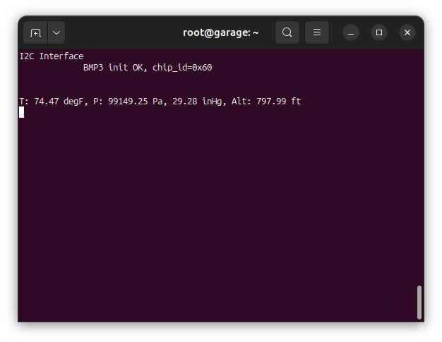
}USART Output
Documentation
This project includes full Doxygen-generated documentation covering the driver’s public API, the I2C communication flow, and the register map, in addition to the inline comments shown throughout this tutorial.
The documentation is available as a separate download in the Project Downloads section below. Once downloaded, view it locally by opening:
docs/html/index.htmlin a web browser.
Project Downloads
The complete project source code used in this tutorial is available for download, along with the browsable Doxygen documentation. The IOC configuration is available above in the Pinouts & Configurations section — regenerate the CubeMX project from it, then drop in the source below.
- Application Source (main.c / main.h)
- MPL3115A2 Driver (mpl3115a2.c / mpl3115a2.h)
- Linker Scripts (STM32F439ZITX_FLASH.ld / STM32F439ZITX_RAM.ld)
Browsable Doxygen documentation for the driver’s public API, the I2C communication flow, and the register map:
If you have questions or run into trouble getting the boards programmed and talking to each other, post in the Tutorial Support forum and I will work through it with you. If project source is not linked in the tutorial, it may be available on request — use the email contact option in the site footer.