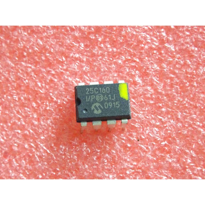
Overview
This STM32 I2C BMP390 tutorial reads barometric pressure and temperature from an Adafruit BMP390 pressure sensor over I2C on a NUCLEO-F439ZI (STM32F439ZIT6), using Bosch Sensortec’s own BMP3 driver, and computes altitude from the pressure reading using the International Standard Atmosphere barometric formula. The firmware configures the sensor for continuous pressure and temperature sampling, polls its data-ready flag, and prints temperature (°F), pressure (Pa and inHg), and altitude (ft) over USART1 once per second.
- Overview
- What You Will Learn
- Prerequisites
- Materials List
- BMP390 Breakout Board Diagram
- Board Diagram
- Project Structure
- Hardware Configuration / Pinouts
- Project Setup
- Code Walkthrough
- Microsecond delay with TIM1
- Retargeting printf to USART1
- Bridging the BMP3 driver to STM32 HAL — register reads
- Bridging the BMP3 driver to STM32 HAL — register writes
- Bridging the BMP3 driver to STM32 HAL — delay callback
- Selecting the I2C interface
- Converting pressure to altitude
- Sensor initialization and configuration
- The main loop
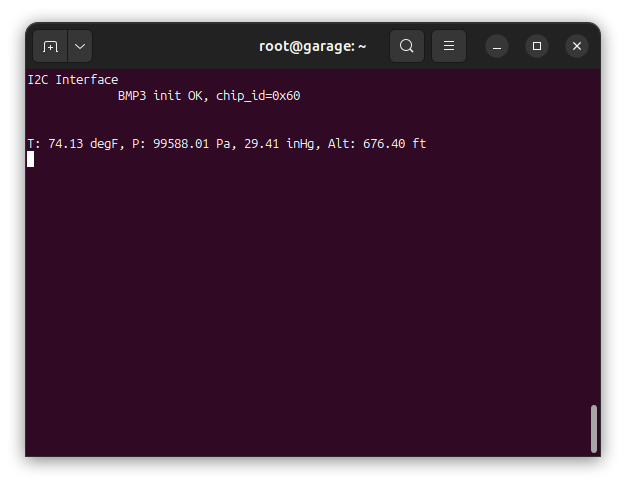
- USART Output
- Documentation
- Project Downloads
What You Will Learn
- Wiring and configuring an Adafruit BMP390 breakout over I2C, and integrating Bosch Sensortec’s vendored BMP3 driver into an STM32 HAL project
- Bridging a vendor driver’s I2C read/write/delay callbacks onto STM32 HAL calls via a small interface/glue layer
- Building a free-running microsecond delay with TIM1 and wiring it into a third-party driver’s delay callback
- Converting BMP390 pressure readings to altitude with the International Standard Atmosphere barometric formula, and why the sea-level pressure reference matters
- Retargeting
printfover USART1 to trace sensor readings on a serial terminal
Prerequisites
This tutorial assumes you can create and build a project in STM32CubeIDE, configure I2C and USART peripherals from CubeMX, and flash a NUCLEO board. You should be comfortable opening a serial terminal at 19200 baud to view the debug output. No prior experience with Bosch’s BMP3 driver or barometric altitude formulas is required — both are covered in the Code Walkthrough.
Materials List
- NUCLEO-F439ZI development board (STM32F439ZIT6, onboard ST-Link — no separate programmer needed)
- Adafruit BMP390 breakout board (I2C, secondary 7-bit address 0x77)
- USB-to-UART adapter (e.g. CP2102 or FTDI) for the serial debug output
- Jumper wires
BMP390 Breakout Board Diagram
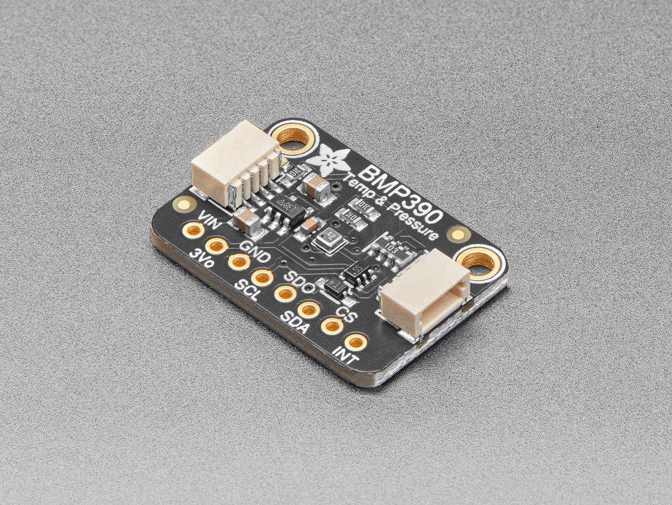
Adafruit’s BMP3XX Learning Guide (PDF) covers the breakout’s wiring, pinout, and usage. Adafruit also publishes the actual board schematic and layout as Eagle CAD source files on GitHub — see the Schematic in the Hardware Configuration section below for the board-specific wiring derived from it.
Board Diagram
Project Structure
./F439_CPP_BMP390_Barometric_Pressure_and_Altimeter_01
├── BMP3
│   ├── bmp3.c
│   ├── bmp3.h
│   ├── bmp3_defs.h
│   └── common
│       ├── common.c
│       └── common.h
├── Core
│   ├── Inc
│   │   ├── i2c_spi_interface.h
│   │   └── main.h
│   └── Src
│       └── main.c
├── LICENSE
├── README.md
├── STM32F439ZITX_FLASH.ld
└── STM32F439ZITX_RAM.ld
Hardware Configuration / Pinouts
Overview
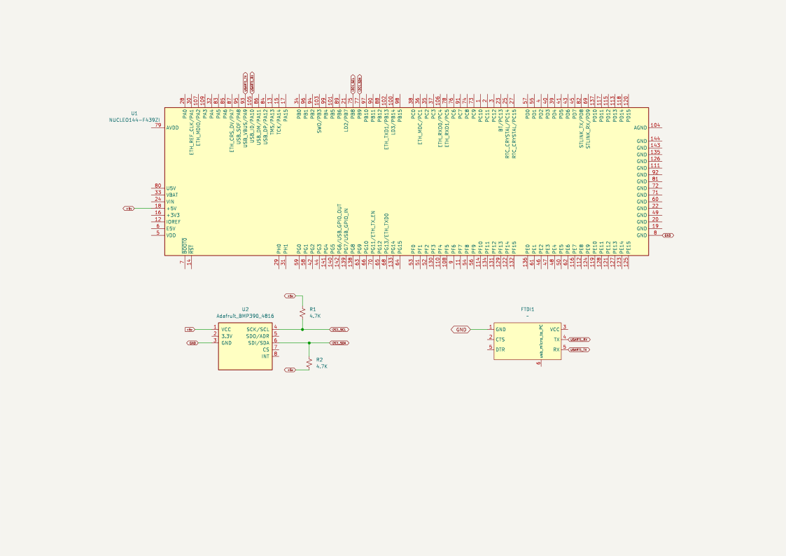
The BMP390 communicates over I2C1 at its secondary 7-bit address 0x77 — the breakout’s SDO/ADR pin selects between 0x76 and 0x77, and per Adafruit’s published schematic it’s pulled to the board’s 3.3V rail by default, which is what selects the secondary address used throughout this tutorial. Only two signal lines are needed — SCL and SDA (labeled SCK/SCL and SDI/SDA on the board’s silkscreen, since the same pins double as SPI in that mode) — plus power and a shared ground with the STM32. A separate USB-to-UART adapter connects to USART1 for the debug trace, since the NUCLEO board’s onboard ST-Link virtual COM port isn’t used for this output.
I2C is open-drain, so SCL and SDA both need pull-up resistors to 3V3. Adafruit’s BMP390 breakout doesn’t need external ones — per its published schematic, it has an onboard bidirectional MOSFET level-shifter with a 10kΩ pull-up pack on both the 3.3V and 5V sides, so the board works correctly at either bus voltage without any extra components.
| Signal | STM32F439 pin | Configuration | Connects to |
|---|---|---|---|
| BMP390 SCL | PB8 | I2C1_SCL, standard mode, 100 kHz | SCL on BMP390 |
| BMP390 SDA | PB9 | I2C1_SDA, standard mode, 100 kHz | SDA on BMP390 |
| USART1_TX | PA9 | Asynchronous, 19200 baud | RX of USB-UART adapter |
| USART1_RX | PA10 | Asynchronous, 19200 baud | TX of USB-UART adapter |
TIM1 has no external pin of its own — it runs purely internally as a 1 µs timebase backing delayUS(), which the BMP3 driver uses for its own delay callback. The system clock runs at 180 MHz, generated from the internal 16 MHz HSI oscillator through the PLL with the power regulator’s Over-Drive mode enabled.
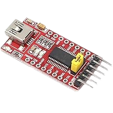
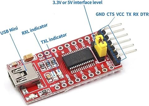
FTDI Pinouts
FTDI to USB Pinout from right to left
- Pin 1 – GND
- Pin 4 – TX
- Pin 5 – RX
- USB Mini – Connect to PC via USB cable
Make sure the jumper is set to 5V — the FTDI board is powered from the USB mini cable, and a computer’s USB port supplies 5V.
Schematic
Pinouts & Configurations
The complete CubeMX pin assignment and peripheral configuration is captured in the IOC report below.
Project Setup
Create a new STM32 project in STM32CubeIDE targeting the STM32F439ZITx (or start from the NUCLEO-F439ZI board selector), then configure the peripherals as follows before generating code:
- Clock: set the RCC oscillator to HSI with the PLL enabled (PLLM=8, PLLN=180, PLLP=/2), and enable the power regulator’s Over-Drive mode. This yields a 180 MHz SYSCLK.
- I2C1: enable I2C mode on PB8/PB9, standard mode, 100 kHz clock speed, 7-bit addressing.
- TIM1: enable it with the internal clock. Set the prescaler to
180-1so it ticks at 1 MHz (1 µs per count), and the period (ARR) to65535. This is the timebase behinddelayUS(), which the BMP3 driver’s delay callback depends on. - USART1: set the mode to Asynchronous at 19200 baud. This puts TX on PA9 and RX on PA10 for the debug trace.
- Generate the project, then copy the
BMP3/driver folder (includingBMP3/common/) andCore/Inc/i2c_spi_interface.hinto the project, and addBMP3/andBMP3/common/to the include paths and source locations. - In
main.h, defineREDIRECT_PRINTFsoprintf()output is retargeted to USART1. - Start TIM1’s base timer once with
HAL_TIM_Base_Start(&htim1), then bind the driver to I2C and initialize it —bmp3_interface_init(&bmp390, BMP3_I2C_INTF)followed bybmp3_init(&bmp390)— before configuring sensor settings and adding the polling loop described below.
Code Walkthrough
The application logic is split across three places: main.c (peripheral setup, sensor configuration, the read/print loop), Core/Inc/i2c_spi_interface.h (a small struct binding an I2C handle and address together), and BMP3/common/common.c — a glue layer that maps Bosch’s own BMP3 driver callbacks onto STM32 HAL calls. The BMP3 driver itself (bmp3.c/bmp3.h/bmp3_defs.h) is vendored from Bosch Sensortec unmodified, so this walkthrough covers the glue and application code around it, not the driver’s internals.
Microsecond delay with TIM1
delayUS() is the same busy-wait pattern used elsewhere in this tutorial series: TIM1 is configured with a prescaler of 180-1, which divides the 180 MHz APB2 timer clock down to exactly 1 MHz — one tick per microsecond. delayUS() resets TIM1’s counter to zero and spins until it reaches the requested number of microseconds. This matters here specifically because the BMP3 driver isn’t STM32-aware — it calls a generic delay_us callback for its own internal timing (sensor power-up and mode-change delays), and that callback has to resolve to a real, accurate microsecond wait on whatever MCU it’s ported to. TIM1’s free-running 1 MHz counter is what makes that wait accurate, rather than approximate.
void delayUS (uint16_t us)
{
	__HAL_TIM_SET_COUNTER(&htim1, 0);  // set the counter value a 0
	while (__HAL_TIM_GET_COUNTER(&htim1) < us);  // wait for the counter to reach the us input in the parameter
}Retargeting printf to USART1
When REDIRECT_PRINTF is defined in main.h, __io_putchar() is compiled in and the C library’s printf() ends up calling it for every character. The implementation is a single blocking HAL_UART_Transmit() call, which is enough to get readable debug output — and, as shown below, the BMP3 driver’s own status messages — on a serial terminal without pulling in a full USART driver layer.
#ifdef REDIRECT_PRINTF
#define PUTCHAR_PROTOTYPE int __io_putchar(int ch)

PUTCHAR_PROTOTYPE
{
  HAL_UART_Transmit(&huart1, (uint8_t *)&ch, 1, 0xFFFF);

  return ch;
}
#endifBridging the BMP3 driver to STM32 HAL — register reads
Bosch’s BMP3 driver never calls STM32 HAL functions directly — it’s platform-agnostic by design, and expects the integrator to supply read/write/delay callbacks matching its own function signatures. bmp3_i2c_read() is that callback for register reads: it casts the driver’s opaque intf_ptr back to the I2C_SPI_Interface struct set up in bmp3_interface_init() (below), then performs the actual transfer with HAL_I2C_Mem_Read(), translating a HAL failure into the driver’s own BMP3_E_COMM_FAIL error code so the rest of the driver can report it consistently.
/*!
 * I2C read function map to COINES platform
 */
BMP3_INTF_RET_TYPE bmp3_i2c_read(uint8_t reg_addr, uint8_t *reg_data, uint32_t len, void *intf_ptr)
{
	HAL_StatusTypeDef halStatus = HAL_OK;
	I2C_SPI_Interface *i2cSpiPtr = (I2C_SPI_Interface *) intf_ptr;
    uint32_t devAddr = i2cSpiPtr->i2cAddress;
    int8_t rslt = BMP3_OK;

    halStatus = HAL_I2C_Mem_Read(i2cSpiPtr->i2c, devAddr, reg_addr, I2C_MEMADD_SIZE_8BIT, reg_data, len, HAL_MAX_DELAY);

    if (halStatus != HAL_OK) {
    	rslt = BMP3_E_COMM_FAIL;
    }

    return rslt;
}Bridging the BMP3 driver to STM32 HAL — register writes
bmp3_i2c_write() is the write-side counterpart, following the same pattern: unpack the interface struct, call HAL_I2C_Mem_Write(), and translate a HAL failure into BMP3_E_COMM_FAIL.
/*!
 * I2C write function map to COINES platform
 */
BMP3_INTF_RET_TYPE bmp3_i2c_write(uint8_t reg_addr, const uint8_t *reg_data, uint32_t len, void *intf_ptr)
{
	HAL_StatusTypeDef halStatus = HAL_OK;
	I2C_SPI_Interface *i2cSpiPtr = (I2C_SPI_Interface *)intf_ptr;
	uint32_t devAddr = i2cSpiPtr->i2cAddress;
    int8_t rslt = BMP3_OK;

   halStatus = HAL_I2C_Mem_Write(i2cSpiPtr->i2c, devAddr, reg_addr, I2C_MEMADD_SIZE_8BIT, (uint8_t *)reg_data, len, HAL_MAX_DELAY);

   if (halStatus != HAL_OK) {
   	rslt = BMP3_E_COMM_FAIL;
   }

   return rslt;
}Bridging the BMP3 driver to STM32 HAL — delay callback
bmp3_delay_us() is the third callback the driver expects, and it’s a thin wrapper around delayUS(). The cast from the driver’s uint32_t period down to delayUS()‘s uint16_t parameter is safe here because every call site in bmp3.c only ever passes 2000 or 5000 microseconds — well under the 65535 limit — not because the cast is safe in general.
/*!
 * Delay function map to COINES platform
 */
void bmp3_delay_us(uint32_t period, void *intf_ptr)
{
    (void)intf_ptr;

    /* delayUS() takes uint16_t (max 65535); every call site in bmp3.c
     * passes 2000 or 5000, well within range, so a direct cast is safe. */
    delayUS((uint16_t)period);
}Selecting the I2C interface
bmp3_interface_init() is what actually wires the three callbacks above into the driver’s bmp3_dev struct, and sets the secondary I2C address (BMP3_ADDR_I2C_SEC, left-shifted for HAL’s 8-bit addressing) into the interface struct passed as intf_ptr. The function also has an SPI branch — the BMP3 driver supports both buses — but this project only calls it with BMP3_I2C_INTF, so bmp3_spi_read()/bmp3_spi_write() are present but never exercised.
BMP3_INTF_RET_TYPE bmp3_interface_init(struct bmp3_dev *bmp3, uint8_t intf)
{
    int8_t rslt = BMP3_OK;

    if (bmp3 != NULL)
    {
        /* Bus configuration : I2C */
        if (intf == BMP3_I2C_INTF)
        {
            printf("I2C Interface\n");
            dev_addr = (BMP3_ADDR_I2C_SEC << 1);
            bmp3->read = bmp3_i2c_read;
            bmp3->write = bmp3_i2c_write;
            bmp3->intf = BMP3_I2C_INTF;

            I2C_SPI_Interface *i2cPtr = bmp3->intf_ptr;
            i2cPtr->i2cAddress = dev_addr;
        }
        /* Bus configuration : SPI */
        else if (intf == BMP3_SPI_INTF)
        {
            printf("SPI Interface\n");
 //           dev_addr = COINES_SHUTTLE_PIN_7;
            bmp3->read = bmp3_spi_read;
            bmp3->write = bmp3_spi_write;
            bmp3->intf = BMP3_SPI_INTF;
        }

        bmp3->delay_us = bmp3_delay_us;
    }
    else
    {
        rslt = BMP3_E_NULL_PTR;
    }

    return rslt;
}Converting pressure to altitude
calculateAltitudeFt() applies the International Standard Atmosphere barometric formula, converting a measured pressure into an altitude relative to a reference sea-level pressure, SEA_LEVEL_PRESSURE_PA. Altitude computed this way is only ever as accurate as that reference: by default the code uses the fixed standard-atmosphere value (101325 Pa), which reports altitude relative to the standard atmosphere, not true elevation, since actual sea-level pressure drifts with the weather.
Defining LOCAL_QNH_CALIBRATION (in Core/Src/main.c, inside USER CODE BEGIN PD so it survives .ioc regeneration) swaps in a value derived from a known reference elevation against this sensor’s own readings on a given day. That’s accurate at calibration time, but the same local-pressure drift means it will need re-deriving the same way later to stay accurate — there’s no way around eventually re-calibrating if you need reasonably true elevation rather than a relative reading.
/**
 * @brief Converts pressure to altitude using the barometric formula
 *        (International Standard Atmosphere model), referenced against
 *        SEA_LEVEL_PRESSURE_PA.
 * @param pressurePa Measured pressure in Pa.
 * @return Altitude in feet relative to the SEA_LEVEL_PRESSURE_PA reference.
 */
static double calculateAltitudeFt(double pressurePa)
{
  double altitudeM = 44330.0 * (1.0 - pow(pressurePa / SEA_LEVEL_PRESSURE_PA, 1.0 / 5.255));

  return altitudeM * 3.28084;
}Sensor initialization and configuration
After the CubeMX-generated peripheral initialization, the USER CODE section starts TIM1’s base timer (required before delayUS() — and therefore the BMP3 driver’s own delays — will work), clears the terminal, and binds the interface and driver together: bmp3_interface_init() wires up the callbacks, then bmp3_init() probes the sensor and reads back its chip ID. On success, the code enables both pressure and temperature measurement with 2x oversampling and a 25 Hz output data rate, then switches the sensor into normal (continuous) mode. Each settings write goes through bmp3_check_rslt(), which prints a human-readable message if the driver reports anything other than success.
  HAL_TIM_Base_Start(&htim1);

  printf("\x1b[2J\x1b[H");	// Clear the dumb terminal screen

  {
    int8_t rslt;
    uint16_t settings_sel;
    struct bmp3_settings settings = { 0 };

    bmp390Intf.i2c = &hi2c1;
    bmp390.intf_ptr = &bmp390Intf;

    bmp3_interface_init(&bmp390, BMP3_I2C_INTF);
    rslt = bmp3_init(&bmp390);

    if (rslt == BMP3_OK)
    {
      printf("BMP3 init OK, chip_id=0x%02X\r\n", bmp390.chip_id);

      settings.press_en = BMP3_ENABLE;
      settings.temp_en = BMP3_ENABLE;
      settings.odr_filter.press_os = BMP3_OVERSAMPLING_2X;
      settings.odr_filter.temp_os = BMP3_OVERSAMPLING_2X;
      settings.odr_filter.odr = BMP3_ODR_25_HZ;

      settings_sel = BMP3_SEL_PRESS_EN | BMP3_SEL_TEMP_EN | BMP3_SEL_PRESS_OS | BMP3_SEL_TEMP_OS | BMP3_SEL_ODR;

      rslt = bmp3_set_sensor_settings(settings_sel, &settings, &bmp390);
      bmp3_check_rslt("bmp3_set_sensor_settings", rslt);

      settings.op_mode = BMP3_MODE_NORMAL;
      rslt = bmp3_set_op_mode(&settings, &bmp390);
      bmp3_check_rslt("bmp3_set_op_mode", rslt);
    }
    else
    {
      printf("BMP3 init FAILED, rslt=%d\r\n", rslt);
    }
}The main loop
Each pass through the loop reads the BMP390’s status register and checks the data-ready (drdy) interrupt flag. When a fresh reading is available, bmp3_get_sensor_data() returns compensated pressure (Pa) and temperature (°C) in one call, which the loop then converts to Fahrenheit, inches of mercury, and altitude before printing all four values at a fixed cursor position (\x1b[5;0H, an ANSI escape sequence) so the line updates in place rather than scrolling. Status is read a second time afterward, since re-reading it is what clears the data-ready flag that was just latched. The print itself is paced with a one-second HAL_Delay(), deliberately decoupled from the sensor’s faster 25 Hz output rate so the terminal stays readable without a screen capture.
  while (1)
  {
    {
      int8_t rslt;
      struct bmp3_status status = { { 0 } };
      struct bmp3_data data = { 0 };

      rslt = bmp3_get_status(&status, &bmp390);

      if ((rslt == BMP3_OK) && (status.intr.drdy == BMP3_ENABLE))
      {
        rslt = bmp3_get_sensor_data(BMP3_PRESS_TEMP, &data, &bmp390);

        if (rslt == BMP3_OK)
        {
          double tempF = (data.temperature * 9.0 / 5.0) + 32.0;
          double altitudeFt = calculateAltitudeFt(data.pressure);
          double pressureInHg = data.pressure * 0.0002952998751;

          printf("\x1b[5;0H");
          printf("T: %.2f degF, P: %.2f Pa, %.2f inHg, Alt: %.2f ft\r\n", tempF, data.pressure, pressureInHg,
                 altitudeFt);
        }

        /* Re-reading status clears the data-ready flag latched above. */
        rslt = bmp3_get_status(&status, &bmp390);
      }

      /* Print cadence is decoupled from the sensor's ODR so the terminal
       * output stays slow enough to read without a screen capture. */
      HAL_Delay(1000);
    }
}USART Output
Documentation
This project includes Doxygen-generated documentation, built directly from the inline comments in main.c, the I2C/interface glue layer, and Bosch’s own documentation comments throughout the BMP3 driver — there are no separate .dox landing pages for this project.
The documentation is available as a separate download in the Project Downloads section below. Once downloaded, view it locally by opening:
docs/html/index.htmlin a web browser.
Project Downloads
The complete project source code used in this tutorial is available for download, along with the browsable Doxygen documentation. The IOC configuration is available above in the Pinouts & Configurations section — regenerate the CubeMX project from it, then drop in the source below.
- Application Source (main.c / main.h / i2c_spi_interface.h)
- BMP3 Driver (bmp3.c / bmp3.h / bmp3_defs.h, vendored from Bosch Sensortec, unmodified)
- BMP3 HAL Glue Layer (BMP3/common/common.c / common.h)
- Linker Scripts (STM32F439ZITX_FLASH.ld / STM32F439ZITX_RAM.ld)
Browsable Doxygen documentation for the application code, the interface glue layer, and the vendored BMP3 driver:
If you have questions or run into trouble getting the boards programmed and talking to each other, post in the Tutorial Support forum and I will work through it with you. If project source is not linked in the tutorial, it may be available on request — use the email contact option in the site footer.