Overview
This tutorial builds an STM32 resistive touch screen interface around the Texas Instruments TSC2046 touch controller, using the Adafruit 5767 breakout and the Adafruit 333 4-wire resistive touch overlay. You will write a C++ SPI driver stack, bridge it into CubeMX-generated main.c, and end up with a working touch panel that switches three LEDs on and off and sounds a buzzer while you hold a BEEP button — all driven from a printed paper layout taped behind the transparent overlay.
Along the way the tutorial covers the parts that are rarely written down: how a 4-wire resistive panel really behaves when nothing is touching it (phantom coordinates and near-zero pressure), why the driver polls instead of trusting the PENIRQ pin, how to turn raw 12-bit coordinates into button zones you measured yourself, and a small startup self-test you can leave in the project as a QA check.
- Overview
- What You Will Learn
- Prerequisites
- Materials List
- Board Diagram
- STM32 Resistive Touch Screen: TSC2046 Breakout and Overlay
- Project Structure
- Hardware Configuration / Pinouts
- Project Setup
- Code Walkthrough
- Building the Touch Layout for the STM32 Resistive Touch Screen
- Running It
- Project Downloads
- Documentation
What You Will Learn
- How to wire an STM32 resistive touch screen — the Adafruit TSC2046 breakout and a 4-wire resistive overlay — to an STM32 Nucleo board over SPI1
- How the TSC2046 measures X, Y and pressure with 12-bit differential conversions, and how a pressure (resistance) value is derived from them
- Why reliable touch detection needs more than “pressure is non-zero” — the pressure band, accepted-area and debounce rules that eliminate phantom touches
- How to calibrate button zones from measured presses and print a paper layout to match
- How to bridge CubeMX-generated plain-C
main.cinto the C++ driver classes without losing code on regeneration - How to add a small
#ifdef-controlled startup self-test to an embedded project - How to combine reusable driver libraries (
STM32BusIO,TSC2046) with a project, and document all of it with one Doxygen run
Prerequisites
You should be comfortable creating and building an STM32CubeIDE project and have a working knowledge of C and basic C++. Familiarity with SPI (clock, MOSI, MISO, chip-select) helps. Debug output is redirected to printf over USART1 through an external FTDI USB-to-serial adapter, per this site’s standard debug setup, and viewed in any serial terminal at 19200 baud.
Materials List
- Nucleo-H753ZI development board
- Adafruit 5767 — TSC2046 resistive touch screen controller breakout
- Adafruit 333 — 4-wire resistive touch screen overlay (flex cable plugs into the breakout’s connector)
- Three 5 mm LEDs (red, green, blue) and three current-limiting resistors (this build used 230 Ω for red and 200 Ω for green and blue)
- One active buzzer module with a 3-pin header (VCC / signal / GND), sounding when its signal pin is pulled low
- Breadboard and jumper wires
- FTDI USB-to-serial adapter, for USART1 debug output
- USB cable for the Nucleo’s ST-LINK connector
- Printer and paper for the touch layout sheet (Downloads below)
Board Diagram
STM32 Resistive Touch Screen: TSC2046 Breakout and Overlay
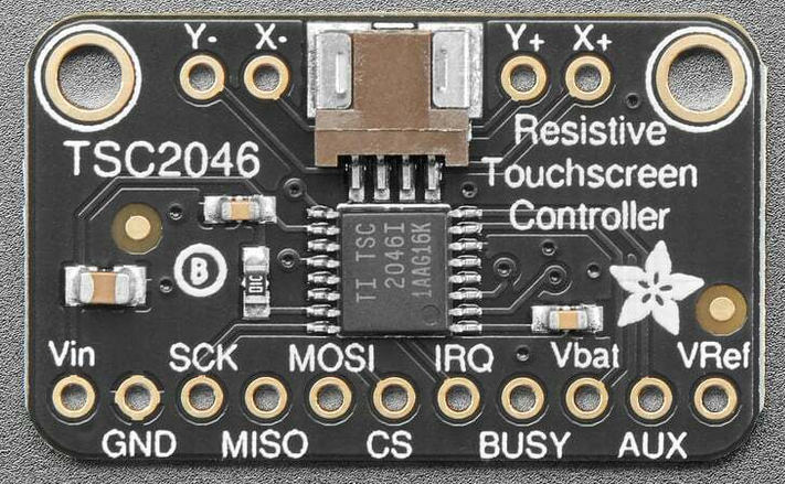
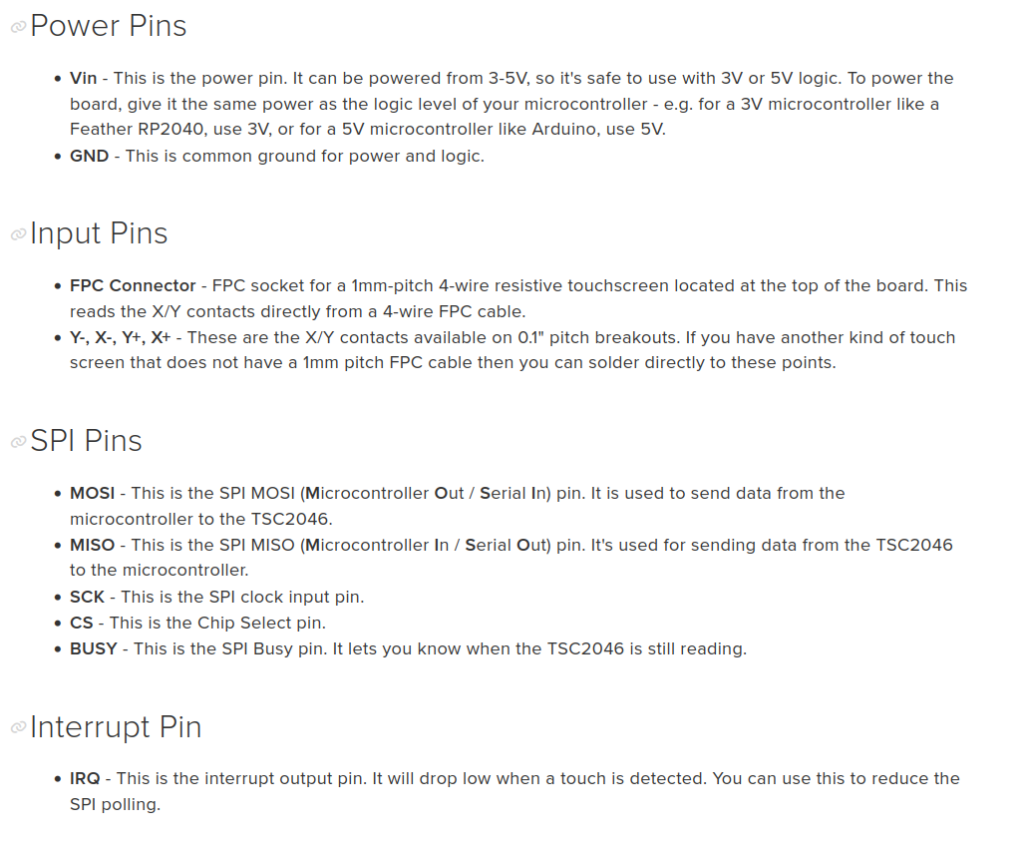
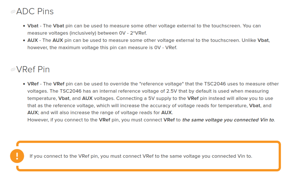
The Adafruit 5767 breakout carries the TSC2046 (the same controller family as the ADS7846) and a flat-flex connector for the overlay. The controller applies a voltage across one layer of the overlay and reads the other layer through its 12-bit ADC to get X, then swaps roles for Y, and finally measures how hard the layers are pressed together to get pressure. Only the six pins used in this tutorial are wired; the pinout diagrams below show every pin on the board.
Project Structure
The project uses two reusable libraries that live in their own folders, STM32BusIO and TSC2046. Each is a separate download (see Getting the Libraries below) so they can be shared with other projects. After you unpack the source zip and both library zips into one project folder the tree looks like this — the two library folders are marked:
H753_CPP_SPI_Resistive_Touch_Screen_Controller/
├── STM32BusIO/                  <- from the STM32_BusIO zip
│   ├── STM32SPIDevice.hpp
│   ├── STM32SPIDevice.cpp
│   ├── STM32BusIORegister.hpp
│   ├── STM32BusIORegister.cpp
│   ├── Doxyfile
│   ├── LICENSE
│   └── README.md
├── TSC2046/                     <- from the STM32_TSC2046 zip
│   ├── TSC2046.hpp
│   ├── TSC2046.cpp
│   ├── Doxyfile
│   ├── LICENSE
│   └── README.md
├── Core/
│   ├── Inc/
│   │   ├── main.h
│   │   ├── entryPointCPP.hpp
│   │   ├── touchZones.h
│   │   └── touchSelfTest.h
│   └── Src/
│       ├── main.c
│       ├── entryPointCPP.cpp
│       ├── touchZones.c
│       └── touchSelfTest.c
├── Doxyfile
├── H753_CPP_SPI_Resistive_Touch_Screen_Controller.ioc
├── H753_CPP_SPI_Resistive_Touch_Screen_Controller.pdf
├── H753_CPP_SPI_Resistive_Touch_Screen_Controller.txt
├── project_mainpage.dox
├── STM32H753ZITX_FLASH.ld
└── STM32H753ZITX_RAM.ld
Hardware Configuration / Pinouts
Overview
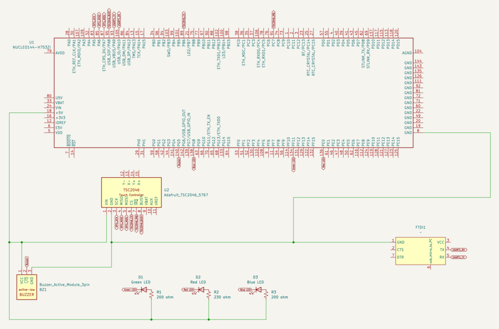
The STM32 resistive touch screen setup talks SPI1 in standard full-duplex master mode. Chip-select is a plain GPIO output driven by the driver so it can hold CS low across a whole command/response transfer. The three LEDs and the buzzer are ordinary GPIO outputs.
| Signal | Nucleo-H753ZI Pin | Notes |
|---|---|---|
| SPI1_SCK | PA5 | SPI clock |
| SPI1_MISO | PA6 | Data from TSC2046 |
| SPI1_MOSI | PA7 | Data to TSC2046 |
| TSC2046_CS | PB6 | GPIO output, active low |
| TSC2046_IRQ | PC7 | GPIO input; wired but not used for detection (see below) |
| TSC2046_BUSY | PA8 | GPIO input; wired but not used |
| LED01 | PF11 | Output; low = LED on |
| LED02 | PE0 | Output; low = LED on |
| LED03 | PG8 | Output; low = LED on |
| Buzzer | PG5 | Output; low = buzzer sounds |
| USART1_TX / RX | PA9 / PA10 | Debug output to the FTDI adapter, 19200 baud |
Power: the breakout’s VCC goes to the Nucleo’s 5V pin and GND to GND. This is safe for the signal pins used here: PA6, PC7 and PA8 are 5 V-tolerant (FT) inputs, and PA5 only ever drives the clock output. Leave VBAT, AUX and VREF unconnected.
The three LEDs are wired from 5V through their own resistor to the LED and then to the GPIO pin, so a low output turns the LED on. The active buzzer module works the same way: its signal pin sounds it when pulled low. All four output pins therefore start high (off) — the project’s .ioc sets their initial pin state to high so nothing lights or beeps during startup.
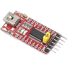
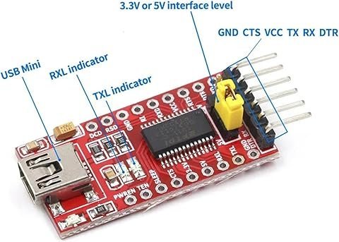
FTDI Pinouts
FTDI to USB Pinout from right to left
- Pin 1 – GND
- Pin 4 – TX
- Pin 5 – RX
- USB Mini – Connect to PC via USB cable
Make sure the jumper is set to 5V — the FTDI board is powered from the USB mini cable, and a computer’s USB port supplies 5V.
Schematic
If the schematic is too small to read clearly, open the full-size image in a new tab and use Ctrl-Scroll to zoom in.
Pinouts & Configurations
The complete CubeMX pin assignment and peripheral configuration is captured in the IOC report below.
Project Setup
Create a new STM32CubeIDE project for the STM32 resistive touch screen, targeting the Nucleo-H753ZI with C++ enabled (main.c itself stays plain C — see the Code Walkthrough). In the .ioc pinout view:
- Enable SPI1 in Full-Duplex Master mode on PA5/PA6/PA7. Set the baud-rate prescaler to 128 (1.5 MBit/s at this board’s clock configuration) — the TSC2046 does not need speed, and a slow clock is forgiving on breadboard wiring.
- Configure PB6 as a GPIO Output labeled
TSC2046_CS, initial level high. - Configure PC7 as a GPIO Input labeled
TSC2046_IRQand PA8 as a GPIO Input labeledTSC2046_BUSY. - Configure PF11 (
LED01), PE0 (LED02), PG8 (LED03) and PG5 (Buzzer) as GPIO Outputs with the initial output level set to High. - Enable USART1 in Asynchronous mode on PA9/PA10 at 19200 baud for the
printfredirect.
Getting the Libraries
The source download contains only this project’s own files. The two driver libraries are shared code, so each is provided as its own download, just like its own repository. STM32_TSC2046 builds on STM32_BusIO, so you need both. Add them to the project like this:
- Create the CubeIDE project as described above, then extract the source zip over it (or copy the files from the zip into the matching folders). Let CubeIDE overwrite the files it generated.
- Extract both library zips (
STM32_BusIO.zipandSTM32_TSC2046.zip) into the project root (the folder that containsCore/). You should now haveSTM32BusIO/andTSC2046/next toCore/, exactly as in the Project Structure tree above. Each zip already contains its own folder name, so extract them “here” — do not create an extra subfolder. - In CubeIDE, right-click the project and choose Refresh (F5). The two new folders appear in the Project Explorer and are compiled automatically.
- Open Project → Properties → C/C++ Build → Settings. Under both MCU GCC Compiler → Include paths and MCU G++ Compiler → Include paths, add
${workspace_loc:/${ProjName}/STM32BusIO}and${workspace_loc:/${ProjName}/TSC2046}. Do this for both the Debug and Release configurations. The code includes the library headers by plain name (for example#include "TSC2046.hpp"), so these paths are what make them resolvable. - Build the project. If you see “TSC2046.hpp: No such file or directory”, the include paths in step 4 are missing or were added to only one of the C/C++ compilers or one configuration.
The libraries are also maintained as separate repositories, STM32_BusIO and STM32_TSC2046. Once they are publicly available on GitHub you can instead clone them straight into the project root instead of using the zip:
cd H753_CPP_SPI_Resistive_Touch_Screen_Controller
git clone https://github.com/jpgroulx/STM32_BusIO.git STM32BusIO
git clone https://github.com/jpgroulx/STM32_TSC2046.git TSC2046
If your own project is itself a git repository, add them as submodules instead so each library keeps its own history:
git submodule add https://github.com/jpgroulx/STM32_BusIO.git STM32BusIO
git submodule add https://github.com/jpgroulx/STM32_TSC2046.git TSC2046
git submodule update --init --recursive
Note the folder names STM32BusIO and TSC2046 given as the last argument — the repository names differ from the folder names, and the Include paths above expect the folder names. When you later clone a project that already uses these as submodules, run git clone --recurse-submodules <project-url> (or git submodule update --init after a plain clone).
Code Walkthrough
How STM32 Resistive Touch Screen Detection Works
An STM32 resistive touch screen gives you three numbers per read: X, Y (each 0–4095) and a pressure value in ohms — lower means harder. The catch is what the panel reports when nothing touches it: because the two layers are floating, the ADC returns junk such as X=0 or X=3855, Y=4095 and pressure between 0 and about 18 Ω. Naively treating “pressure > 0” as touched reports constant phantom touches. Real touches on this panel measured roughly 110–600 Ω, so the loop accepts a touch only when all of these hold:
- Pressure is inside a real-touch band: at least 40 Ω (idle junk reads 0–18 Ω) and below 1500 Ω (light touches).
- The point is inside the accepted X/Y area, which rejects the extreme idle readings.
- A zone is acted on only after two consecutive samples agree, and a press ends only after three consecutive untouched samples (debounce, at a 10 ms poll).
The TSC2046’s PENIRQ pin is not used for detection. On this panel it is disturbed by the polled SPI conversions themselves, so polling pressure is more reliable. The pin is wired anyway so you can experiment with it.
A 4-wire resistive panel can only report one point. If two fingers touch, the controller reports a point between them — this is a hardware limitation, not a driver bug — so this project is deliberately single-touch and needs no RTOS.
C/C++ bridge: entryPointCPP
CubeMX regenerates main.c as plain C every time the .ioc changes, so the C++ driver is reached through a small pair of C-callable functions declared extern "C". The driver object is created with new inside initTSC2046(), called from main() after MX_SPI1_Init() — never as a global, because global constructors run before main() and before any peripheral is configured. Every bridge function checks a ready flag first, so a call made before initTSC2046() is harmless. See the C++ integration post for the background on this pattern.
/**
 * @file entryPointCPP.cpp
 * @brief Implementation of the C-callable TSC2046 entry points.
 *
 *  Created on: Sep 15, 2026
 *      Author: johng
 */

#include "entryPointCPP.hpp"
#include "TSC2046.hpp"

extern SPI_HandleTypeDef hspi1;

/** @brief The single TSC2046 driver instance, constructed in initTSC2046(). */
static TSC2046 *tsc2046 = nullptr;

/** @brief Set once initTSC2046() runs; guards every bridge function below against use-before-init. */
static bool tsc2046Ready = false;

void initTSC2046(void) {
	tsc2046 = new TSC2046(&hspi1, TSC2046_CS_GPIO_Port, TSC2046_CS_Pin);
	tsc2046->begin();
	tsc2046Ready = true;
}

bool tsc2046IsReady(void) {
	return tsc2046Ready;
}

bool tsc2046GetPoint(int16_t *x, int16_t *y, float *pressure) {
	if (tsc2046 == nullptr || !tsc2046Ready) {
		return false;
	}
	TSC2046TouchPoint point = tsc2046->getPoint();
	*x = point.x;
	*y = point.y;
	*pressure = point.pressure;
	return true;
}

bool tsc2046IsTouched(void) {
	if (tsc2046 == nullptr || !tsc2046Ready) {
		return false;
	}
	return tsc2046->isTouched();
}

void tsc2046EnableInterrupts(bool enable) {
	if (tsc2046 == nullptr || !tsc2046Ready) {
		return;
	}
	tsc2046->enableInterrupts(enable);
}

void tsc2046SetVRef(float vref) {
	if (tsc2046 == nullptr || !tsc2046Ready) {
		return;
	}
	tsc2046->setVRef(vref);
}

void tsc2046SetTouchedThreshold(float touchedThresholdOhms) {
	if (tsc2046 == nullptr || !tsc2046Ready) {
		return;
	}
	tsc2046->setTouchedThreshold(touchedThresholdOhms);
}

bool tsc2046ReadTemperatureC(float *celsius) {
	if (tsc2046 == nullptr || !tsc2046Ready) {
		return false;
	}
	*celsius = tsc2046->readTemperatureC();
	return true;
}

bool tsc2046ReadBatteryVoltage(float *volts) {
	if (tsc2046 == nullptr || !tsc2046Ready) {
		return false;
	}
	*volts = tsc2046->readBatteryVoltage();
	return true;
}

bool tsc2046ReadAuxiliaryVoltage(float *volts) {
	if (tsc2046 == nullptr || !tsc2046Ready) {
		return false;
	}
	*volts = tsc2046->readAuxiliaryVoltage();
	return true;
}Touch zones
touchZones maps raw coordinates to the printed buttons. The boundaries are constants measured from real presses on the panel, not the geometry on the paper, because resistive panels are not perfectly linear — the BEEP row at the very bottom, for example, reads Y values up to about 3560. The left half of each row is OFF and the right half is ON; BEEP spans the full width.
/**
 * @file touchZones.h
 * @brief Maps raw TSC2046 X/Y readings to the printed button zones on the panel overlay.
 *
 * The panel has LED 1/2/3 buttons, each split OFF|ON, plus a full-width BEEP
 * zone. Boundaries come from measured touches on the actual panel, not the
 * printed geometry -- resistive panels are not perfectly linear.
 *
 *  Created on: Sep 18, 2026
 *      Author: johng
 */

#ifndef INC_TOUCHZONES_H_
#define INC_TOUCHZONES_H_

#include <stdint.h>

#ifdef __cplusplus
extern "C" {
#endif

/** @brief The button zones on the printed panel, or TOUCH_ZONE_NONE for a point outside them. */
typedef enum {
	TOUCH_ZONE_NONE = 0,
	TOUCH_ZONE_LED1_OFF,
	TOUCH_ZONE_LED1_ON,
	TOUCH_ZONE_LED2_OFF,
	TOUCH_ZONE_LED2_ON,
	TOUCH_ZONE_LED3_OFF,
	TOUCH_ZONE_LED3_ON,
	TOUCH_ZONE_BEEP
} touchZone_t;

/**
 * @brief Classifies a raw touch position into a button zone.
 * @param x Raw 12-bit X (0-4095).
 * @param y Raw 12-bit Y (0-4095).
 * @retval The zone containing the point, or TOUCH_ZONE_NONE if it falls
 *         outside the calibrated active area.
 */
touchZone_t touchZoneFromPoint(int16_t x, int16_t y);

/**
 * @brief Gives a short printable name for a zone.
 * @param zone The zone to name.
 * @retval A short printable name for the zone, e.g. "LED 2 ON", or "none" for TOUCH_ZONE_NONE.
 */
const char *touchZoneName(touchZone_t zone);

#ifdef __cplusplus
}
#endif

#endif /* INC_TOUCHZONES_H_ */
/**
* @file touchZones.c
* @brief Zone boundaries and classification for the printed panel layout.
*
* Created on: Sep 18, 2026
* Author: johng
*/
#include "touchZones.h"
/* Accepted touch area. Deliberately generous: the BEEP row sits at the very bottom of
* the panel and its presses read Y ~3340-3600, so a tight limit rejected them. Idle
* (untouched) junk readings are already rejected by the pressure band in main.c. */
/** @brief Lowest accepted raw X. */
#define TOUCH_X_MIN 300
/** @brief Highest accepted raw X. */
#define TOUCH_X_MAX 3700
/** @brief Lowest accepted raw Y. */
#define TOUCH_Y_MIN 300
/** @brief Highest accepted raw Y. */
#define TOUCH_Y_MAX 3650
/** @brief Raw X that separates the OFF (left) half from the ON (right) half, from measured button centers. */
#define TOUCH_X_SPLIT 2060
/* Row boundaries, from measured presses on the panel with the printed layout:
* LED1 Y ~580-880, LED2 ~1660-1790, LED3 ~2420-2700, BEEP ~3115-3560. */
/** @brief Raw Y boundary between the LED 1 row and the LED 2 row. */
#define TOUCH_Y_LED1_LED2 1285
/** @brief Raw Y boundary between the LED 2 row and the LED 3 row. */
#define TOUCH_Y_LED2_LED3 2075
/** @brief Raw Y boundary between the LED 3 row and the BEEP row. */
#define TOUCH_Y_LED3_BEEP 2900
touchZone_t touchZoneFromPoint(int16_t x, int16_t y) {
if (x < TOUCH_X_MIN || x > TOUCH_X_MAX || y < TOUCH_Y_MIN || y > TOUCH_Y_MAX) {
return TOUCH_ZONE_NONE;
}
if (y >= TOUCH_Y_LED3_BEEP) {
return TOUCH_ZONE_BEEP; /* full width: any X */
}
int right = (x >= TOUCH_X_SPLIT);
if (y < TOUCH_Y_LED1_LED2) {
return right ? TOUCH_ZONE_LED1_ON : TOUCH_ZONE_LED1_OFF;
}
if (y < TOUCH_Y_LED2_LED3) {
return right ? TOUCH_ZONE_LED2_ON : TOUCH_ZONE_LED2_OFF;
}
return right ? TOUCH_ZONE_LED3_ON : TOUCH_ZONE_LED3_OFF;
}
const char *touchZoneName(touchZone_t zone) {
switch (zone) {
case TOUCH_ZONE_LED1_OFF: return "LED 1 OFF";
case TOUCH_ZONE_LED1_ON: return "LED 1 ON";
case TOUCH_ZONE_LED2_OFF: return "LED 2 OFF";
case TOUCH_ZONE_LED2_ON: return "LED 2 ON";
case TOUCH_ZONE_LED3_OFF: return "LED 3 OFF";
case TOUCH_ZONE_LED3_ON: return "LED 3 ON";
case TOUCH_ZONE_BEEP: return "BEEP";
default: return "none";
}
}main.c
Everything below lives inside the CubeMX USER CODE blocks, so regenerating the project does not remove it. First the output polarity macros, the includes, and the startup sequence:
/* USER CODE BEGIN Includes */
#include <stdio.h>
#include <math.h>
#include "entryPointCPP.hpp"
#include "touchZones.h"
#ifdef TOUCH_SELFTEST_ENABLE
#include "touchSelfTest.h"
#endif
/* USER CODE END Includes */

/* USER CODE BEGIN PD */
/** @brief Pin level that turns an output ON. LEDs are wired 5V -> resistor -> LED -> GPIO, so low = lit; the buzzer module sounds when its signal pin is low. */
#define OUT_ON   GPIO_PIN_RESET
/** @brief Pin level that turns an output OFF (LED dark, buzzer silent). */
#define OUT_OFF  GPIO_PIN_SET
/* USER CODE END PD */

/* USER CODE BEGIN 2 */

  printf("\x1b[2J\x1b[H");	// Clear the dumb terminal screen

  outputsAllOff();
  initTSC2046();
  printf("TSC2046 touch controller initialized.\r\n");
#ifdef TOUCH_SELFTEST_ENABLE
  touchSelfTestRunAll();
#endif
  printf("Touch the panel...\r\n");

  /* Poll state: only report while touched, plus one line on release. */
  bool wasTouched = false;
  uint32_t lastPrintMs = 0;
  touchZone_t lastZone = TOUCH_ZONE_NONE;
  touchZone_t candidateZone = TOUCH_ZONE_NONE;
  uint8_t candidateCount = 0;

/* USER CODE END 2 */Then the polling loop, which applies the pressure band, the accepted-area check and the two-sample settle rule described above. Note that the LED/buzzer action runs before the printf: at 19200 baud a printed line blocks the loop for about 25 ms, which would make the outputs feel sluggish.
/* USER CODE BEGIN 3 */

    // Poll every 10 ms. "Touched" needs ALL of:
    //  - pressure in a real-touch band: >= 40 ohm (idle/untouched junk reads 0-18 ohm,
    //    measured) and < 1500 ohm (light touches); real touches measured ~110-600 ohm.
    //  - the point inside the accepted touch area (idle junk gives X=0 / X=3855 etc.).
    // PENIRQ is NOT used: on this panel it is disturbed by the polled SPI reads.
    // A zone is acted on after 2 consecutive samples agree (fast enough for quick taps),
    // and a press ends after 3 consecutive untouched samples. The LED/buzzer action runs
    // BEFORE any printf: at 19200 baud one printed line blocks the loop for ~25 ms.
    static uint32_t lastPollMs = 0;
    static uint8_t untouchedCount = 0;
    if (HAL_GetTick() - lastPollMs >= 10)
    {
      lastPollMs = HAL_GetTick();
      int16_t x = 0, y = 0;
      float pressure = 0.0f;
      bool rawTouched = false;
      touchZone_t zone = TOUCH_ZONE_NONE;
      if (tsc2046GetPoint(&x, &y, &pressure))
      {
        zone = touchZoneFromPoint(x, y);
        rawTouched = isfinite(pressure) && pressure >= 40.0f && pressure < 1500.0f
                     && zone != TOUCH_ZONE_NONE;
      }

      if (rawTouched)
      {
        untouchedCount = 0;

        if (zone == candidateZone)
        {
          if (candidateCount < 255) candidateCount++;
        }
        else
        {
          candidateZone = zone;
          candidateCount = 1;
        }

        if (candidateCount >= 2 && candidateZone != lastZone)
        {
          lastZone = candidateZone;
          wasTouched = true;
          applyZoneAction(lastZone);                       // act first...
          printf("Zone: %s\r\n", touchZoneName(lastZone)); // ...then print
        }
        else if (wasTouched && HAL_GetTick() - lastPrintMs >= 200)
        {
          lastPrintMs = HAL_GetTick();
          printf("Touch: X=%4d  Y=%4d  Pressure=%ld ohm\r\n", x, y, (long)pressure);
        }
      }
      else
      {
        if (untouchedCount < 255) untouchedCount++;
        candidateCount = 0;
        candidateZone = TOUCH_ZONE_NONE;

        if (wasTouched && untouchedCount >= 3)
        {
          wasTouched = false;
          lastZone = TOUCH_ZONE_NONE;
          HAL_GPIO_WritePin(Buzzer_GPIO_Port, Buzzer_Pin, OUT_OFF);   // release ends the beep
          printf("Released\r\n");
        }
      }
    }
  }
/* USER CODE END 3 */And the two helper functions in USER CODE 4. The LEDs latch — an ON zone turns an LED on and an OFF zone turns it off — while the buzzer sounds only for as long as you hold the BEEP zone:
/* USER CODE BEGIN 4 */


/**
 * @brief Drives all three LEDs and the buzzer to their OFF level (LEDs dark, buzzer silent).
 */
static void outputsAllOff(void)
{
  HAL_GPIO_WritePin(LED01_GPIO_Port, LED01_Pin, OUT_OFF);
  HAL_GPIO_WritePin(LED02_GPIO_Port, LED02_Pin, OUT_OFF);
  HAL_GPIO_WritePin(LED03_GPIO_Port, LED03_Pin, OUT_OFF);
  HAL_GPIO_WritePin(Buzzer_GPIO_Port, Buzzer_Pin, OUT_OFF);
}

/**
 * @brief Applies the action for a settled touch zone. LEDs latch: an ON zone
 *        turns that LED on and an OFF zone turns it off. The buzzer sounds
 *        only while the BEEP zone is held, so any non-BEEP zone silences it.
 * @param zone The zone that just settled (see touchZoneFromPoint()).
 */
static void applyZoneAction(touchZone_t zone)
{
  switch (zone)
  {
  case TOUCH_ZONE_LED1_ON:  HAL_GPIO_WritePin(LED01_GPIO_Port, LED01_Pin, OUT_ON);  break;
  case TOUCH_ZONE_LED1_OFF: HAL_GPIO_WritePin(LED01_GPIO_Port, LED01_Pin, OUT_OFF); break;
  case TOUCH_ZONE_LED2_ON:  HAL_GPIO_WritePin(LED02_GPIO_Port, LED02_Pin, OUT_ON);  break;
  case TOUCH_ZONE_LED2_OFF: HAL_GPIO_WritePin(LED02_GPIO_Port, LED02_Pin, OUT_OFF); break;
  case TOUCH_ZONE_LED3_ON:  HAL_GPIO_WritePin(LED03_GPIO_Port, LED03_Pin, OUT_ON);  break;
  case TOUCH_ZONE_LED3_OFF: HAL_GPIO_WritePin(LED03_GPIO_Port, LED03_Pin, OUT_OFF); break;
  default: break;
  }
  HAL_GPIO_WritePin(Buzzer_GPIO_Port, Buzzer_Pin, (zone == TOUCH_ZONE_BEEP) ? OUT_ON : OUT_OFF);

/* USER CODE END 4 */Startup self-test
touchSelfTest.c runs three quick checks at boot when TOUCH_SELFTEST_ENABLE is defined in main.h: an SPI transfer completes, the controller’s response is correctly framed (the top bit and trailing zeros of the 16-bit reply), and 25 idle samples produce no touches. Comment out the define to build without it. A temperature self-test was deliberately left out — the TSC2046’s on-chip temperature reading is only a rough indication and is not accurate enough to pass or fail a test on; the driver’s Doxygen documents this. The source is in the downloads.
Building the Touch Layout for the STM32 Resistive Touch Screen
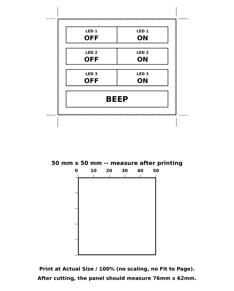
The STM32 resistive touch screen is just a transparent overlay, so the buttons are a paper sheet placed behind it. Print the layout below at 100% scale (no “fit to page”), check that the printed 50 mm × 50 mm reference square really measures 50 mm, cut the sheet to the panel size and attach it to the back of the touch panel.
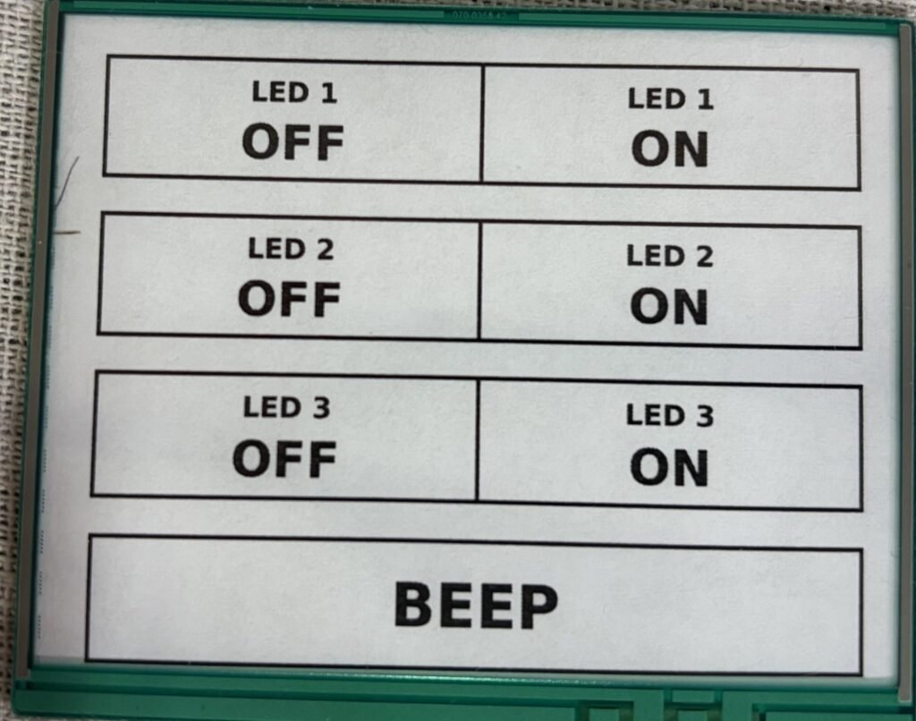
Leave both protective films on the touch panel as shipped — the rear film is what lets the sheet stick to the back. The photo below shows the finished result: the printed sheet behind the overlay, oriented with the narrow side top-to-bottom and the wide side left-to-right.
Running It
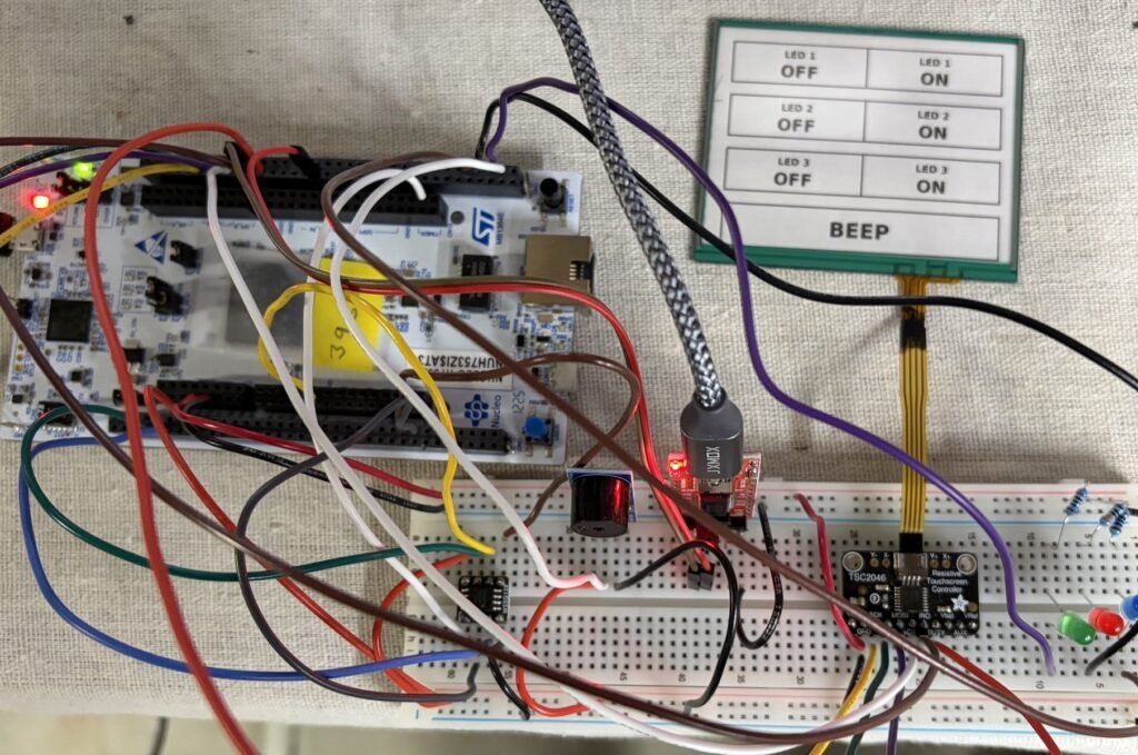
Here is the finished build: the Nucleo-H753ZI, the TSC2046 breakout, the buzzer and LEDs, and the touch panel with its printed layout attached. The small W25Q128 flash breakout also on the breadboard is left over from an earlier QSPI flash tutorial — it isn’t part of this project, and was deliberately left in place while wiring the touchscreen to confirm the two SPI buses don’t conflict.
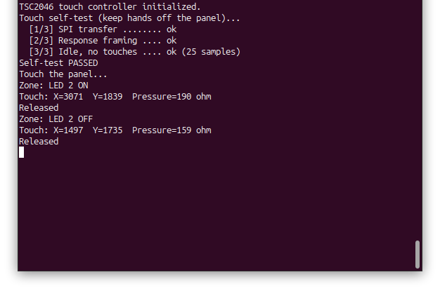
Open a serial terminal at 19200 baud, reset the board to run the STM32 resistive touch screen demo and touch the buttons. LED zones latch the LEDs; hold BEEP to sound the buzzer. The terminal prints the self-test result at startup, then a Zone: line when a button registers, periodic Touch: lines with raw X, Y and pressure while held, and Released when you lift off:
Project Downloads
The complete STM32 resistive touch screen project used in this tutorial is available for download in three parts. The source download contains this project’s own files; the two library downloads, STM32_BusIO and STM32_TSC2046, contain the driver libraries that go into the project root (see Getting the Libraries above).
- Project source:
Core/sources, Doxygen configuration, IOC file and IOC report, linker scripts - Libraries:
STM32_BusIO(STM32BusIO/) andSTM32_TSC2046(TSC2046/), one zip each - Doxygen documentation (docs/html/index.html)
Browsable Doxygen documentation covering the project code and both libraries:
Documentation
The documentation is generated from the project source and both libraries in a single Doxygen run, so index.html covers everything. It is included as a separate download above; extract it and open:
docs/html/index.htmlin a web browser. If you would rather generate it yourself, install Doxygen and run doxygen Doxyfile from the project root once the libraries are in place — the project Doxyfile already lists both library folders as inputs. Each library also has its own Doxyfile and README.md so it can be documented on its own.
If you have questions or run into trouble getting the boards programmed and talking to each other, post in the Tutorial Support forum and I will work through it with you. If project source is not linked in the tutorial, it may be available on request — use the email contact option in the site footer.