Disclosure: Bridgetek provided the IDK-BT817-70A kit used in this tutorial on running the BT817 over SPI from an STM32 free of charge with no obligations. Bridgetek did not fund this tutorial nor did they review or approve its content, and every setting, problem and result described here comes from my own bench.
Overview
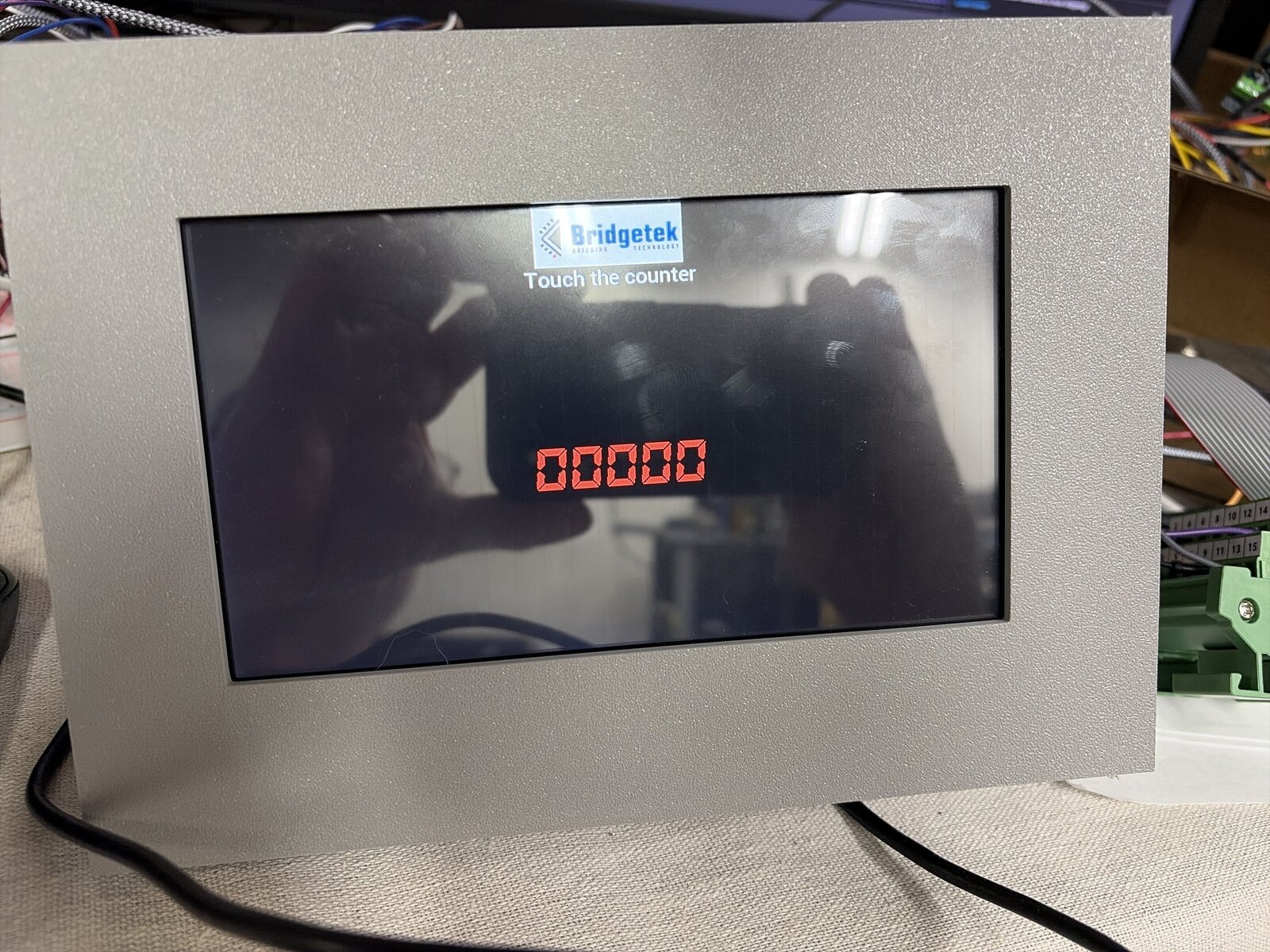
This tutorial drives the Bridgetek BT817 over SPI from an STM32 for the first time: a NUCLEO-H753ZI takes over the host connector CN8 of the ME817EV board from the IDK-BT817-70A kit, proves that the BT817 is alive with a start-up check of its own, and then runs Bridgetek’s own “simple” demo through Bridgetek’s EVE library. The demo puts the Bridgetek logo and a touch counter on the 7-inch, 800 x 480 DP-0701-01A panel.
Running the vendor’s example first is deliberate. Before writing any screens of your own, you want to know that the wiring, the switches, the power and the library work, using code that the vendor has already tested. Then every later problem is in your own code. This part is therefore mostly about bring-up: the BT817’s start-up sequence, what each step looks like on a logic analyzer, and the problems I hit on my bench, from a pin in the wrong place to a ground connection that turned out to cause almost every strange symptom.
This is Part 2 of the series. Bridgetek BT817 EVE Kit Setup with EVE Screen Designer set up the kit and proved the panel from a PC; do that first. A future post will replace the vendor demo with our own touch screens. The NUCLEO-H753ZI pinout page shows where every pin used here is on the board.
- Overview
- What You Will Learn
- Prerequisites
- Materials List
- Board Diagram
- The ME817EV Host Connector CN8
- Project Structure
- Hardware Configuration / Pinouts
- Project Setup
- Code Walkthrough
- Running It: the BT817 over SPI on the Board
- Troubleshooting: What Went Wrong on My Bench
- Logic Analyzer Captures
- Project Downloads
- Documentation
- What's Next
What You Will Learn
- How to wire the ME817EV host connector CN8 to a NUCLEO-H753ZI on SPI1, with PD# and INT#, and set SW2 and JP1 for a microcontroller host
- The BT817 start-up sequence: the PD# reset, the host commands that start its clock, the boot time, and the reads of
REG_ID,REG_CPURESETand the chip ID - How to write a small start-up check that tells you exactly which step failed, with retries for transient SPI errors
- How to add Bridgetek’s EVE library and its “simple” demo to an STM32CubeIDE project, with the compiler settings that select the BT817 and the panel
- What the BT817 over SPI looks like on a logic analyzer, including a failed start-up
- The problems that cost me time: a wrong MOSI pin, a misplaced PD# wire, the touch engine held in reset, the ground between the boards, and an SPI speed the library set behind CubeMX’s back
Prerequisites
You should be comfortable creating and building an STM32CubeIDE project and have a working knowledge of C and of SPI (clock, MOSI, MISO and a chip select). The Bridgetek BT817 kit should already be assembled and working as described in Bridgetek BT817 EVE Kit Setup with EVE Screen Designer, including the touch cable. Debug output is redirected to printf over USART1 through an external FTDI USB-to-serial adapter, per this site’s standard debug setup, and viewed in any serial terminal at 19200 baud. A logic analyzer is optional, but it is the fastest way to see why a bring-up fails.
Materials List
- NUCLEO-H753ZI development board
- Bridgetek IDK-BT817-70A kit: the ME817EV board, the VA-1001-01A LCD adapter and the DP-0701-01A 7-inch capacitive touch panel, assembled as in Part 1
- USB-C cable and a 5 V USB supply (or a PC port) for the ME817EV’s CN11 connector
- FTDI USB-to-serial adapter, for USART1 debug output
- USB cable for the Nucleo’s ST-LINK connector
- Wiring for the connections shown in the schematic below, including a short, heavy ground connection between the two boards
- Optional: a logic analyzer
Board Diagram
The ME817EV Host Connector CN8
In Part 1 the BT817 was driven by the PC through the FT4222H bridge on the ME817EV. For an STM32 host, the same BT817 lines come out on the 2 x 8 header CN8, and switch SW2 decides which of the two hosts is connected. Pin 1 is SCK, top left in the photo, and every pin has its name printed beside it.
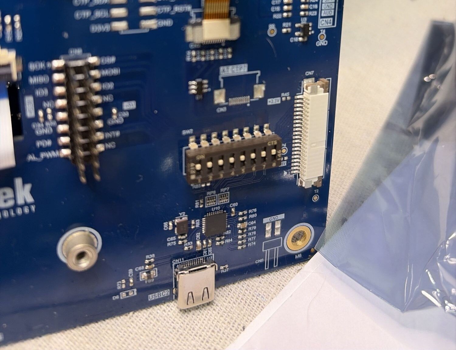
This tutorial uses eight of the sixteen pins:
| CN8 pin | Signal | Direction | NUCLEO-H753ZI |
|---|---|---|---|
| 1 | SCK | STM32 to BT817 | PA5 (SPI1_SCK) |
| 2 | CS# | STM32 to BT817 | PB6 (GPIO output, label EVE CS#) |
| 3 | MISO | BT817 to STM32 | PA6 (SPI1_MISO) |
| 4 | MOSI | STM32 to BT817 | PB5 (SPI1_MOSI) |
| 11, 12 | GND | GND | |
| 13 | PD# | STM32 to BT817 | PD15 (GPIO output, label EVE PD#) |
| 14 | INT# | BT817 to STM32 | PF3 (EXTI3, label EVE_INT, not used by the demo) |
| 5 to 10, 15, 16 | IO2, IO3, GPIO and 5V_HOST | not connected |
Set the ME817EV for a microcontroller host and its own power supply:
- SW2 all OFF. This disconnects the FT4222H (the PC) from the BT817 host lines and hands them to CN7/CN8.
- JP1 on 1-2. The ME817EV takes its power from the USB-C connector CN11. Leave CN8 pin 10 (5V_HOST) unconnected: the Nucleo does not power the display.
- Connect the grounds properly. The two boards have separate supplies, and the backlight draws most of the ME817EV’s current. Besides the two CN8 ground pins, add a short, heavy ground connection between the ME817EV and the Nucleo. The troubleshooting section explains why this one matters so much.
PD# is the BT817’s power-down input: low holds the chip in reset, high lets it run. The firmware starts it low and pulses it at every start. INT# is an open-drain interrupt output; it is wired and configured with a pull-up for later parts, but the demo does not use it.
The Bridgetek documents for this part, copied here so the links keep working. The ME817EV datasheet has the CN8 pinout, SW2 and JP1:
The BT817 datasheet has the host commands, the SPI memory read format and the start-up sequence used by the start-up check:
The programming guide describes the registers, the display list and the co-processor commands the demo uses:
Project Structure
The project’s own files are one download and Bridgetek’s EVE library is another, so the library can be shared with other projects (see Getting the Library below). Bridgetek’s demo is part of the project download, in its own EVE_Example/ folder. After you unpack the source zip and the library zip into one project folder the tree looks like this, with the library folder marked:
H753_CPP_SPI_BT817_EVE_01/
├── STM32_Bridgetek_EVE_API/             <- from the STM32_Bridgetek_EVE_API zip
│   ├── include/
│   │   ├── BT81x.h
│   │   ├── BT82x.h
│   │   ├── EVE.h
│   │   ├── EVE_config.h
│   │   ├── FT80x.h
│   │   ├── FT81x.h
│   │   ├── FT8xx.h
│   │   ├── HAL.h
│   │   ├── MCU.h
│   │   └── Platform.h
│   ├── ports/
│   │   └── eve_arch_stm32/
│   │       ├── EVE_MCU_STM32CUBE.c
│   │       ├── EVE_MCU_STM32CUBE_QUADSPI.c
│   │       ├── EVE_MCU_STM32CUBE_SPI.c
│   │       └── README.md
│   ├── source/
│   │   ├── EVE_API.c
│   │   └── EVE_HAL.c
│   ├── LICENSE
│   ├── README.md
│   └── UPSTREAM_README.md
├── Core/
│   ├── Inc/
│   │   └── main.h
│   └── Src/
│       └── main.c
├── EVE_Example/
│   ├── LICENSE
│   ├── README.txt
│   ├── eve_example.c
│   ├── eve_example.h
│   ├── eve_fonts.c
│   ├── eve_images.c
│   ├── touch.c
│   └── touch.h
├── H753_CPP_SPI_BT817_EVE_01.ioc
├── H753_CPP_SPI_BT817_EVE_01.pdf
├── H753_CPP_SPI_BT817_EVE_01.txt
├── LICENSE
├── README.md
├── STM32H753ZITX_FLASH.ld
└── STM32H753ZITX_RAM.ld
Hardware Configuration / Pinouts
Overview
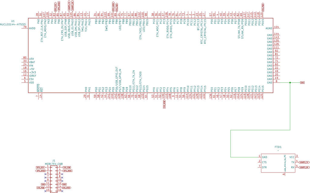
The project uses SPI1 for the BT817, two GPIO outputs for its chip select and power-down pins, one EXTI input for its interrupt pin, and USART1 for the terminal.
| Signal | NUCLEO-H753ZI pin | Notes |
|---|---|---|
| ME817EV CN8-1 SCK | PA5 | SPI1_SCK, 12 Mbit/s |
| ME817EV CN8-3 MISO | PA6 | SPI1_MISO |
| ME817EV CN8-4 MOSI | PB5 | SPI1_MOSI. Not PA7: on this board PA7 goes to the Ethernet PHY |
| ME817EV CN8-2 CS# | PB6 | GPIO output, starts high (not selected) |
| ME817EV CN8-13 PD# | PD15 | GPIO output, starts low (BT817 held in reset) |
| ME817EV CN8-14 INT# | PF3 | EXTI3, falling edge, pull-up; not used by the demo |
| ME817EV CN8-11, CN8-12 GND | GND | Plus a short, heavy ground connection between the boards |
| FTDI RX / TX | PA9 / PA10 | USART1_TX / USART1_RX, debug output at 19200 baud |
The NUCLEO-H753ZI pinout page shows where these pins are on the board.
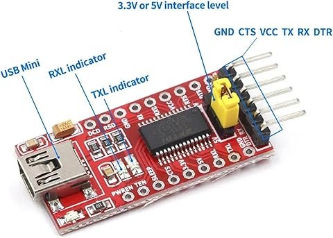
FTDI Pinouts
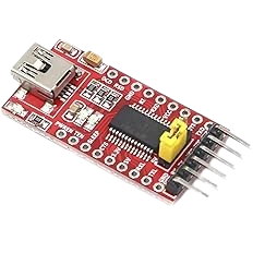
FTDI to USB Pinout from right to left
- Pin 1 – GND
- Pin 4 – TX
- Pin 5 – RX
- USB Mini – Connect to PC via USB cable
Make sure the jumper is set to 5V — the FTDI board is powered from the USB mini cable, and a computer’s USB port supplies 5 V. The FTDI TX goes to the Nucleo’s PA10 (USART1_RX) and the FTDI RX to PA9 (USART1_TX).
Schematic
If the schematic is too small to read clearly, open the full-size image in a new tab and use Ctrl-Scroll to zoom in. A vector (SVG) version is also available.
Pinouts & Configurations
The complete CubeMX pin assignment and peripheral configuration is captured in the IOC report below.
Project Setup
Create a new STM32CubeIDE project for the NUCLEO-H753ZI. In the .ioc pinout view:
- Enable SPI1 as Full-Duplex Master on PA5 (SCK), PA6 (MISO) and PB5 (MOSI), Hardware NSS Signal disabled, MSB first, clock polarity low and clock phase on the first edge (SPI mode 0). Set the data size to 8 bits: on the STM32H7, CubeMX starts SPI at 4 bits. Set the prescaler to 16, which gives 12 Mbit/s here.
- Set PB6 as GPIO_Output with the user label
EVE CS#and output level High, so the BT817 is not selected at start-up. - Set PD15 as GPIO_Output with the user label
EVE PD#and output level Low, so the BT817 stays in reset until the firmware starts it. - Set PF3 as GPIO_EXTI3 with the user label
EVE_INT, falling edge, pull-up. The demo does not use it. - Enable USART1 in Asynchronous mode on PA9/PA10 at 19200 baud for the
printfredirect. - Generate the code.
The labels matter. CubeMX turns EVE CS# and EVE PD# into the macros EVE_CS__Pin, EVE_CS__GPIO_Port, EVE_PD__Pin and EVE_PD__GPIO_Port in main.h. These are the names Bridgetek’s own STM32 example projects use, and the library’s STM32 port drives the two pins through exactly those macros. With any other label the library does not compile.
Getting the Library
The source download contains this project’s own files and Bridgetek’s demo. Bridgetek’s EVE library is shared code, so it is its own download, just like its own repository:
- Extract the source zip over the project, then extract the library zip into the project root (the folder that contains
Core/). You should now haveSTM32_Bridgetek_EVE_API/andEVE_Example/next toCore/, exactly as in the Project Structure tree above. Let CubeIDE overwrite the files it generated. - In CubeIDE, right-click the project and choose Refresh (F5).
- Make both folders source folders: Project → Properties → C/C++ General → Paths and Symbols → Source Location → Add Folder, then tick
STM32_Bridgetek_EVE_APIandEVE_Example. A source folder shows a small gear on its icon in the Project Explorer. - Open Project → Properties → C/C++ Build → Settings. Under both MCU GCC Compiler → Include paths and MCU G++ Compiler → Include paths, add
${workspace_loc:/${ProjName}/STM32_Bridgetek_EVE_API/include}and${workspace_loc:/${ProjName}/EVE_Example}. Do this for both the Debug and Release configurations. - In the same Settings page, under MCU GCC Compiler → Preprocessor (and MCU G++ Compiler → Preprocessor), add the four defined symbols in the table below, again for Debug and Release.
- Build the project. If you see “EVE.h: No such file or directory”, the include paths in step 4 are missing or were added to only one compiler or one configuration. If the build ends with “undefined reference to EVE_Init” or “undefined reference to eve_example”, a folder in step 3 is not a source folder. An error such as “MODULE_TYPE must be configured” or “EVE_DISP_* parameters must be configured” means a symbol from step 5 is missing or misspelled.
| Symbol | What it selects |
|---|---|
FT8XX_TYPE=BT817 | The EVE chip: the BT817 and its register map |
PANEL_TYPE=DP_0701_01A | The panel: 800 x 480 and its timing (pixel clock, porches, sync widths) |
PLATFORM_STM32_CUBE=1 | The STM32Cube port, single-channel SPI (4 would select QUADSPI) |
PLATFORM_STM32_CUBE_CHANNEL=1 | SPI1, so the port uses the hspi1 handle that CubeMX generates |
The library is Bridgetek’s portable EVE library, Eve-MCU-Dev, cut down to what an STM32Cube project needs (MIT licence, Bridgetek’s copyright kept). EVE_Example/ is Bridgetek’s “simple” demo and touch snippet from the same repository, copied unchanged (MIT, see its LICENSE and README.txt). The library’s README lists the one change that matters for this part: Bridgetek’s STM32 port switched SPI to a faster prescaler of its own after start-up, which overrode the CubeMX setting; this copy always keeps the speed set in CubeMX. The troubleshooting section below shows why. The library is kept as its own git repository; in my project it is a git submodule, which keeps its history separate from the project’s.
Code Walkthrough
How the Project Fits Together
main.c: the CubeMX set-up, our own start-up check (eveChipIdTest()), which talks to the BT817 directly over SPI with no library, theprintfredirect, three small functions the demo needs, and the call to the demo.EVE_Example/(Bridgetek): the demo itself.eve_example()starts the BT817 through the library, calibrates touch, loads a font and the logo, and shows the counter screen.STM32_Bridgetek_EVE_API(library): starts the BT817 (EVE_Init()), sets up the panel timing, and turns calls likeEVE_CMD_TEXT()into SPI writes to the BT817’s command FIFO.
Everything in main.c lives inside the CubeMX USER CODE blocks, so regenerating the project does not remove it. After the peripheral init, main() clears the terminal, runs the start-up check and starts the demo, which never returns:
  /* USER CODE BEGIN 2 */

  printf("\x1b[2J\x1b[H");	// Clear the dumb terminal screen

  /* Start-up check: prints REG_ID, REG_CPURESET and the chip ID, stops on failure. */
  if (runChipIdTest)
  {
    eveChipIdTest();
  }

  printf("Starting the Bridgetek simple example.\r\n");
  eve_example();

/* USER CODE END 2 */runChipIdTest is a static const bool near the top of main.c, true by default. The demo resets and starts the BT817 again in EVE_Init() either way, so the check can be switched off once the hardware is known to work.
The Start-Up Check: Addresses and Commands
The check is written straight from the BT817 datasheet, so it needs only a few addresses and command bytes:
#define EVE_REG_ID           0x302000UL /**< REG_ID, always reads 0x7C once booted */
#define EVE_REG_CPURESET     0x302020UL /**< REG_CPURESET, 0 = engines running */
#define EVE_RAM_CHIPID       0x0C0000UL /**< Chip ID, 08 17 01 00 for a BT817 */
#define EVE_REG_ID_VALUE     0x7CU      /**< Expected REG_ID value */
#define EVE_CMD_ACTIVE       0x00U      /**< Host command ACTIVE */
#define EVE_CMD_CLKEXT       0x44U      /**< Host command CLKEXT (external crystal) */
#define EVE_CMD_RST_PULSE    0x68U      /**< Host command RST_PULSE (core reset) */
#define EVE_CMD_CLKSEL       0x61U      /**< Host command CLKSEL (system clock select) */
#define EVE_CLKSEL_72MHZ     0x46U      /**< CLKSEL parameter: 6 x 12 MHz, PLL range 1 (Bridgetek EVE_HAL.c) */
#define EVE_SPI_RETRIES      3U         /**< Attempts per SPI transaction */
#define EVE_SPI_TIMEOUT_MS   10U        /**< HAL timeout per SPI transaction */
#define EVE_BOOT_TIMEOUT_MS  300U       /**< Boot can take up to 300 ms (4.9.4) */
#define EVE_ENGINE_TIMEOUT_MS 3000U     /**< Wait for REG_CPURESET; the touch engine waits for the touch controller to boot */
#define EVE_MAX_READ_BYTES 4U /**< Largest read this test needs */The Start-Up Check: SPI Transactions
Every exchange with the BT817 is one SPI transaction: CS# low, the bytes out and in at the same time, CS# high. eveSpiTransaction() does exactly that, and retries the whole transaction on a transient error (busy, timeout or a transfer-error flag), up to three times. A failure that cannot be fixed by trying again, or three failed attempts, prints the HAL status and the SPI error code and stops in Error_Handler():
/**
 * @brief Runs one complete SPI transaction with the BT817 (CS low, transfer, CS high).
 *        Retries the whole transaction on transient errors, up to EVE_SPI_RETRIES,
 *        then reports the reason and calls Error_Handler().
 * @param tx Bytes to send (must hold length bytes).
 * @param rx Buffer for the bytes clocked back (must hold length bytes).
 * @param length Number of bytes to clock.
 * @note Not thread-safe or ISR-safe: blocking HAL_SPI_TransmitReceive on hspi1
 *       and the EVE_CS pin, with no locking. Called from main() before the loop.
 */
static void eveSpiTransaction(const uint8_t *tx, uint8_t *rx, uint16_t length)
{
  HAL_StatusTypeDef status = HAL_ERROR;

  for (uint32_t attempt = 1U; attempt <= EVE_SPI_RETRIES; attempt++)
  {
    HAL_GPIO_WritePin(EVE_CS__GPIO_Port, EVE_CS__Pin, GPIO_PIN_RESET);
    status = HAL_SPI_TransmitReceive(&hspi1, (uint8_t *)tx, rx, length, EVE_SPI_TIMEOUT_MS);
    HAL_GPIO_WritePin(EVE_CS__GPIO_Port, EVE_CS__Pin, GPIO_PIN_SET);

    if (status == HAL_OK)
    {
      return;
    }
    printf("EVE SPI: attempt %lu of %u failed (HAL status %d, SPI error 0x%08lX)\r\n",
           (unsigned long)attempt, EVE_SPI_RETRIES, (int)status,
           (unsigned long)HAL_SPI_GetError(&hspi1));
    if (!eveSpiIsTransient(status))
    {
      break;
    }
  }
  printf("EVE SPI: giving up, the transfer did not complete.\r\n");
  Error_Handler();
}A host command is three bytes: the command, a parameter (0 for most commands) and a 0. Reading BT817 memory has a fixed format (datasheet section 4.1.3): three address bytes with the top two bits 00 for a read, one dummy byte, then the data:
/**
 * @brief Sends a 3-byte BT817 host command (command, parameter, 0x00).
 * @param command Host command byte, e.g. EVE_CMD_CLKEXT or EVE_CMD_ACTIVE.
 * @param parameter Second byte; 0x00 for most commands, the clock setting for CLKSEL.
 * @note Not thread-safe or ISR-safe (see eveSpiTransaction()).
 */
static void eveHostCommand(uint8_t command, uint8_t parameter)
{
  uint8_t tx[3] = { command, parameter, 0x00U };
  uint8_t rx[3];

  eveSpiTransaction(tx, rx, (uint16_t)sizeof(tx));
}

/**
 * @brief Reads bytes from BT817 memory: 3 address bytes (top two bits 00 = read),
 *        one dummy byte, then the data (datasheet 4.1.3).
 * @param address 22-bit BT817 memory address.
 * @param data Destination for the bytes read.
 * @param length Number of bytes to read, 1 to EVE_MAX_READ_BYTES.
 * @note Not thread-safe or ISR-safe (see eveSpiTransaction()).
 */
static void eveReadMemory(uint32_t address, uint8_t *data, uint16_t length)
{
  uint8_t tx[4U + EVE_MAX_READ_BYTES] = { 0 };
  uint8_t rx[4U + EVE_MAX_READ_BYTES] = { 0 };

  if ((data == NULL) || (length == 0U) || (length > EVE_MAX_READ_BYTES))
  {
    printf("eveReadMemory: bad argument (data %p, length %u)\r\n", (void *)data, length);
    Error_Handler();
    return;
  }
  tx[0] = (uint8_t)((address >> 16) & 0x3FU);
  tx[1] = (uint8_t)(address >> 8);
  tx[2] = (uint8_t)address;
  /* tx[3] = dummy byte, then zeros while the data is clocked in */
  eveSpiTransaction(tx, rx, (uint16_t)(4U + length));
  memcpy(data, &rx[4], length);
}During boot some registers take a while to reach their final value, so eveWaitForRegister() polls a register every millisecond until it holds the expected value or the time runs out, and hands back the last value it read for the error message:
/**
 * @brief Polls an 8-bit BT817 register until it holds the expected value or a timeout passes.
 * @param address Register address.
 * @param expected Value to wait for.
 * @param timeoutMs How long to keep polling, in milliseconds.
 * @param lastValue Receives the last value read (for the failure report).
 * @return true if the expected value was read in time, false on timeout.
 * @note Not thread-safe or ISR-safe (see eveSpiTransaction()).
 */
static bool eveWaitForRegister(uint32_t address, uint8_t expected, uint32_t timeoutMs, uint8_t *lastValue)
{
  uint32_t start = HAL_GetTick();

  do
  {
    eveReadMemory(address, lastValue, 1U);
    if (*lastValue == expected)
    {
      return true;
    }
    HAL_Delay(1U);
  } while ((HAL_GetTick() - start) < timeoutMs);

  return false;
}The Start-Up Check: BT817 over SPI, Step by Step
eveChipIdTest() follows the BT817’s start-up sequence from the datasheet:
- Reset. PD# low for 20 ms, then high (the datasheet asks for at least 5 ms).
- Clock. Four host commands:
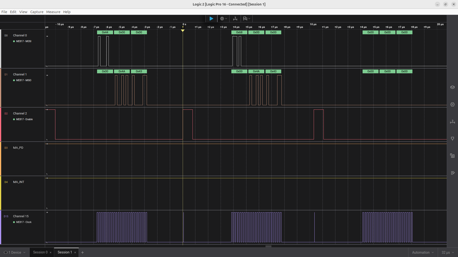
CLKEXT(0x44, use the external 12 MHz crystal),CLKSEL(0x61 0x46, a system clock of 6 x 12 = 72 MHz),RST_PULSE(0x68) andACTIVE(0x00). This is the order Bridgetek’s ownEVE_HAL.cuses. - Boot. Booting takes up to 300 ms, and until it is done only
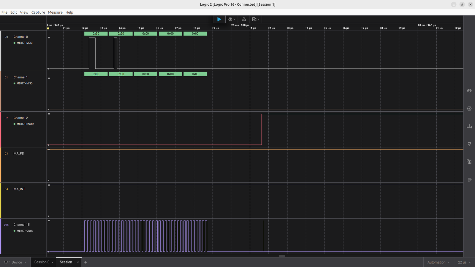
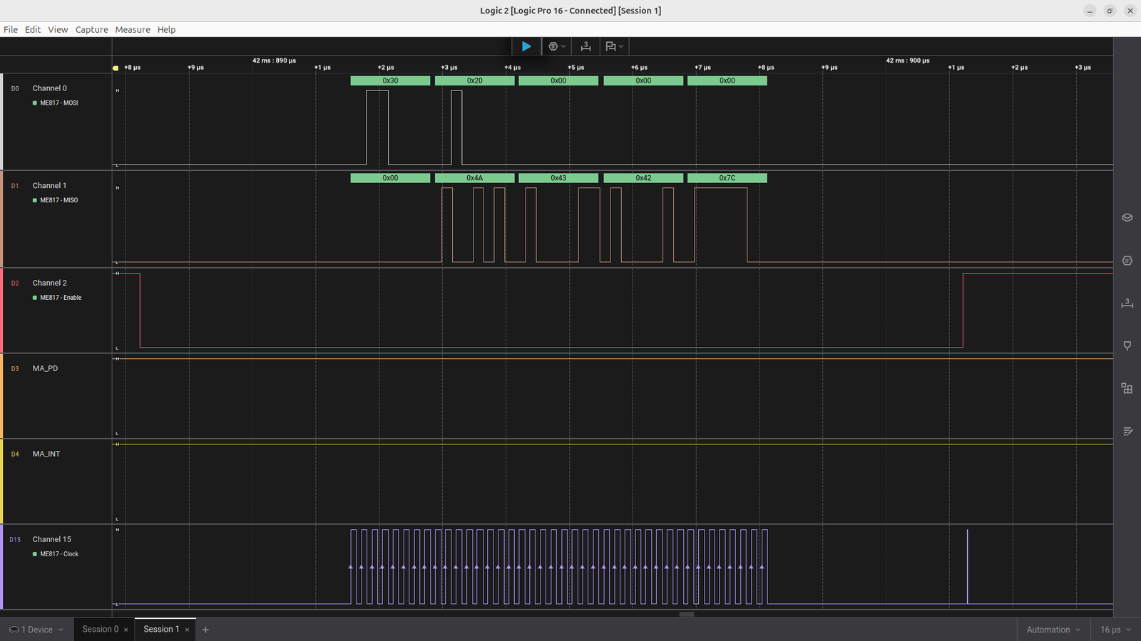
REG_IDandREG_CPURESETmay be read. The check pollsREG_IDuntil it reads 0x7C. - Engines.
REG_CPURESEThas one bit per engine: bit 0 the co-processor, bit 1 the touch engine, bit 2 the audio engine. All three are running when it reads 0. The touch engine waits for the panel’s touch controller, so the check allows up to 3 seconds and prints how long it took. - Chip ID. The four bytes at 0x0C0000 read 08 17 01 00 on a BT817 (a BT818 reads 08 18 01 00).
/**
 * @brief BT817 bring-up test: resets the chip on PD#, starts its clock, waits for
 *        boot, then checks REG_ID (0x7C), REG_CPURESET (0) and the chip ID (08 17 01 00).
 *        Prints PASS, or the reason for the failure and calls Error_Handler().
 * @note Not thread-safe or ISR-safe: blocking SPI and HAL_Delay(); call once from
 *       main() after MX_GPIO_Init() and MX_SPI1_Init(), before the main loop.
 */
static void eveChipIdTest(void)
{
  static const uint8_t expectedChipId[4] = { 0x08U, 0x17U, 0x01U, 0x00U };
  uint8_t value = 0U;
  uint8_t chipId[4] = { 0U };

  printf("BT817 SPI chip-ID test (H753_CPP_SPI_BT817_EVE_01)\r\n");

  /* 1. Hardware reset: PD# low (MX_GPIO_Init() already starts it low), >= 5 ms (4.9.4) */
  HAL_GPIO_WritePin(EVE_PD__GPIO_Port, EVE_PD__Pin, GPIO_PIN_RESET);
  HAL_Delay(20U);
  HAL_GPIO_WritePin(EVE_PD__GPIO_Port, EVE_PD__Pin, GPIO_PIN_SET);
  HAL_Delay(20U);

  /* 2. Clock enable (4.2.3): CLKEXT, CLKSEL (72 MHz), RST_PULSE, then ACTIVE, the order
   *    Bridgetek's EVE_HAL.c uses (CLKEXT itself can trigger a system reset);
   *    wait >= 20 ms (4.9.3.5) */
  eveHostCommand(EVE_CMD_CLKEXT, 0x00U);
  eveHostCommand(EVE_CMD_CLKSEL, EVE_CLKSEL_72MHZ);
  eveHostCommand(EVE_CMD_RST_PULSE, 0x00U);
  eveHostCommand(EVE_CMD_ACTIVE, 0x00U);
  HAL_Delay(20U);

  /* 3. Boot takes up to 300 ms; only REG_ID and REG_CPURESET may be read (4.9.4) */
  if (!eveWaitForRegister(EVE_REG_ID, EVE_REG_ID_VALUE, EVE_BOOT_TIMEOUT_MS, &value))
  {
    printf("FAIL: REG_ID reads 0x%02X, expected 0x%02X within %u ms.\r\n",
           value, EVE_REG_ID_VALUE, EVE_BOOT_TIMEOUT_MS);
    evePrintNoAnswerHelp(value);
    Error_Handler();
    return;
  }
  printf("REG_ID       = 0x%02X  OK\r\n", value);

  /* REG_CPURESET bits: 0 = coprocessor, 1 = touch engine, 2 = audio engine (AN_033) */
  uint32_t engineStart = HAL_GetTick();
  if (!eveWaitForRegister(EVE_REG_CPURESET, 0x00U, EVE_ENGINE_TIMEOUT_MS, &value))
  {
    printf("FAIL: REG_CPURESET reads 0x%02X, expected 0x00 within %u ms"
           " (bit0 coprocessor, bit1 touch, bit2 audio still in reset).\r\n",
           value, EVE_ENGINE_TIMEOUT_MS);
    Error_Handler();
    return;
  }
  printf("REG_CPURESET = 0x%02X  OK (after %lu ms)\r\n", value,
         (unsigned long)(HAL_GetTick() - engineStart));

  /* 4. Chip ID at 0C0000h (5.2) */
  eveReadMemory(EVE_RAM_CHIPID, chipId, (uint16_t)sizeof(chipId));
  printf("Chip ID      = %02X %02X %02X %02X\r\n", chipId[0], chipId[1], chipId[2], chipId[3]);
  if (memcmp(chipId, expectedChipId, sizeof(chipId)) != 0)
  {
    printf("FAIL: expected 08 17 01 00 (BT817). A BT818 reads 08 18 01 00.\r\n");
    Error_Handler();
    return;
  }
  printf("PASS: BT817 found over SPI.\r\n");
}When REG_ID never reads 0x7C, the BT817 is not answering at all, and the check prints a short checklist. A value of 0x00 or 0xFF means nothing is driving MISO, which is a wiring, switch or power problem, not a timing problem:
/**
 * @brief Prints the wiring checklist used when the BT817 does not answer.
 * @param misoValue The last byte read back, to show whether MISO looks stuck.
 */
static void evePrintNoAnswerHelp(uint8_t misoValue)
{
  if ((misoValue == 0x00U) || (misoValue == 0xFFU))
  {
    printf("  MISO reads 0x%02X: nothing is answering on the SPI lines.\r\n", misoValue);
  }
  printf("  Check the wiring against the schematic (ME817EV CN8 to the Nucleo):\r\n");
  printf("    CN8-1 SCK = PA5, CN8-2 CS# = PB6, CN8-3 MISO = PA6, CN8-4 MOSI = PB5,\r\n");
  printf("    CN8-13 PD# = PD15, CN8-11/12 GND, plus a heavy ground between the boards.\r\n");
  printf("  ME817EV: SW2 all OFF, JP1 on 1-2, USB-C power in CN11.\r\n");
}Two Small Additions for Bridgetek’s Code
Bridgetek’s library prints its debug messages with a bare \n. On a serial terminal that starts each line where the previous one ended, so the output runs down the screen like a staircase. The printf redirect therefore sends a \r before any \n that does not already have one:
#ifdef REDIRECT_PRINTF
#define PUTCHAR_PROTOTYPE int __io_putchar(int ch)

/**
 * @brief  Sends one printf character to the USART1 console.
 * @details A bare '\n' (as printed by the Bridgetek library's DEBUG_PRINTF)
 *          is sent as "\r\n" so terminal lines start at the left margin.
 *          "\r\n" from our own printf calls is passed through unchanged.
 *          Thread safety: not thread-safe or ISR-safe; it keeps the previous
 *          character in a static variable and blocks on the UART.
 * @param  ch Character to send.
 * @retval The character sent.
 */
PUTCHAR_PROTOTYPE
{
  static int previousChar = 0;
  uint8_t carriageReturn = (uint8_t)'\r';

  if ((ch == '\n') && (previousChar != '\r'))
  {
    HAL_UART_Transmit(&huart1, &carriageReturn, 1, 0xFFFF);
  }
  HAL_UART_Transmit(&huart1, (uint8_t *)&ch, 1, 0xFFFF);
  previousChar = ch;

  return ch;
}
#endifBridgetek’s touch snippet (touch.c) can store the touch calibration so it is not repeated after every reset. It asks the platform for three functions. This project has no storage for it yet, so they report “not supported”, and the demo asks for a new calibration after every reset:
/**
 * @brief  Tell the Bridgetek example whether touch calibration can be stored.
 * @details Called by the vendor example (touch.c). This project has no
 *          storage for calibration yet, so it reports "not supported" and
 *          the example asks for a new calibration after every reset.
 *          Thread safety: safe from any context; it touches no shared state.
 * @retval 1 Storing touchscreen settings is not supported.
 */
int8_t platform_calib_init(void)
{
  return 1;
}

/**
 * @brief  Store touch calibration values (not supported in this project).
 * @param  calib Calibration values from the BT817 (unused).
 * @details Thread safety: safe from any context; it touches no shared state.
 * @retval -1 The settings were not stored.
 */
int8_t platform_calib_write(struct touchscreen_calibration *calib)
{
  (void)calib;
  return -1;
}

/**
 * @brief  Read stored touch calibration values (not supported in this project).
 * @param  calib Where the values would be written (left unchanged).
 * @details Thread safety: safe from any context; it touches no shared state.
 * @retval -1 No stored settings are available.
 */
int8_t platform_calib_read(struct touchscreen_calibration *calib)
{
  (void)calib;
  return -1;
}Bridgetek’s Simple Demo
eve_example() is the whole demo: start the BT817, calibrate touch, load a custom font for the digits and the Bridgetek logo into the BT817’s RAM, then draw the counter screen for ever. If the calibration fails, it stops in an endless loop, and with the library’s debug output off it does so silently:
void eve_example(void)
{
    uint32_t font_end;

    // Initialise the display
    EVE_Init();

    // Calibrate the display
    DEBUG_PRINTF("Calibrating display...\n");
    if (eve_calibrate() != 0)
    {
        DEBUG_PRINTF("Exception...\n");
        while(1);
    }

    // Load fonts and images
    DEBUG_PRINTF("Loading font...\n");
    font_end = eve_init_fonts();
    DEBUG_PRINTF("Loading images...\n");
    eve_load_images(font_end);

    // Start example code
    DEBUG_PRINTF("Starting demo:\n");
    eve_display();
}eve_display() builds the screen as one co-processor command list (logo, “Touch the counter”, five digits from the custom font, with tag 100 on the digits), then waits for a touch and counts. Because it waits for any tag and redraws straight away, the counter keeps counting for as long as you hold your finger on it. That is how Bridgetek wrote it: a commented-out line at the top of the loop changes it to one count per press.
        while (eve_read_tag(&key) == 0);

        if (key == 100)
        {
            counter++;
            if (counter == 100000)
            {
                counter = 0;
            }
        }
    } while (1);
}Running It: the BT817 over SPI on the Board
Set the ME817EV as described above (SW2 all OFF, JP1 on 1-2), power it from CN11, build and flash the project and open a serial terminal at 19200 baud. The start-up check prints each step, then hands over to the demo:
BT817 SPI chip-ID test (H753_CPP_SPI_BT817_EVE_01)
REG_ID       = 0x7C  OK
REG_CPURESET = 0x00  OK (after 0 ms)
Chip ID      = 08 17 01 00
PASS: BT817 found over SPI.
Starting the Bridgetek simple example.The panel then shows Bridgetek’s calibration screen: tap each of the three dots as it appears. After that the demo loads its font and logo and shows the counter screen. Hold a finger on the digits and they count up.
Troubleshooting: What Went Wrong on My Bench
None of this worked the first time. These are the problems in the order I hit them, with the symptom you would see and what fixed it.
MOSI on the Wrong Pin
Symptom: FAIL: REG_ID reads 0x00, and MISO reads 0x00. The BT817 never sees a valid command, so it never answers. SPI1_MOSI is PB5 in this project. On the NUCLEO-H753ZI the pin that many SPI examples use for SPI1_MOSI, PA7, is connected to the Ethernet PHY, so do not use it here.
PD# on the Wrong Pin
Symptom: the start-up check fails on some resets and passes on others. The logic analyzer showed the cause: in a failing run PD# stayed low the whole time, so the BT817 was held in power-down and never booted, and MISO showed nothing but crosstalk from the neighbouring wire. The PD# wire was on the wrong pin. On the correct pin (PD15) the check passed on 20 resets in a row. A pin that “sometimes works” is often a pin that is not connected to what you think.
The Touch Engine Held in Reset
Symptom: REG_ID is fine, but REG_CPURESET stays at 0x02: bit 1, the touch engine, is still in reset. The BT817’s touch engine waits for the panel’s own touch controller. Power-cycling the ME817EV (unplugging CN11 for a few seconds) cleared it, and I have not seen it since the ground below was fixed. This is why the check waits up to 3 seconds and names the bit that is still set.
The Ground Between the Boards
This was the big one. The ME817EV and the Nucleo have separate supplies, and the signal wiring’s ground pins alone were not enough. With a weak ground, the BT817 saw false chip-select edges at its end of the wiring even though CS# looked clean where I measured it. The symptoms looked unrelated:
- a chip ID of
0B FF FF FFinstead of08 17 01 00on some resets - replies on MISO that restart in the middle of a transaction
- a “co-processor exception” from the library, or the demo stopping right after the calibration screen
- random lines on the panel
A short, heavy ground connection directly between the ME817EV and the Nucleo fixed all of them at once. If you see any of these, fix the ground before you change any code.
An SPI Speed Set Behind CubeMX’s Back
Symptom: the start-up check passes, but the demo hangs. Bridgetek’s original STM32 port changed the SPI prescaler itself after start-up, to 24 Mbit/s on this board, whatever CubeMX said. At 24 Mbit/s the demo hung on my wiring, even with the ground fixed. The library in this tutorial therefore keeps the CubeMX speed, so the value in the .ioc is the value you get. On my setup 12 Mbit/s (prescaler 16) is the fastest speed that works reliably. Bridgetek’s programming guide asks for an SPI clock below 11 MHz until the BT817’s clock is running, so 12 Mbit/s is slightly above that; if your start-up is unreliable, use prescaler 32 (6 Mbit/s).
Logic Analyzer Captures
These captures show the start-up check of this project on the SPI lines at 12 Mbit/s. The channels are MOSI, MISO, Enable (CS#), PD#, INT# and Clock (SCK). They were taken before CLKSEL was added to the check, so the current code sends one more three-byte host command, 0x61 0x46 0x00, between CLKEXT and RST_PULSE. Everything else is identical.
The overview: PD# low for 20 ms, then high, then the host commands and the first reads.
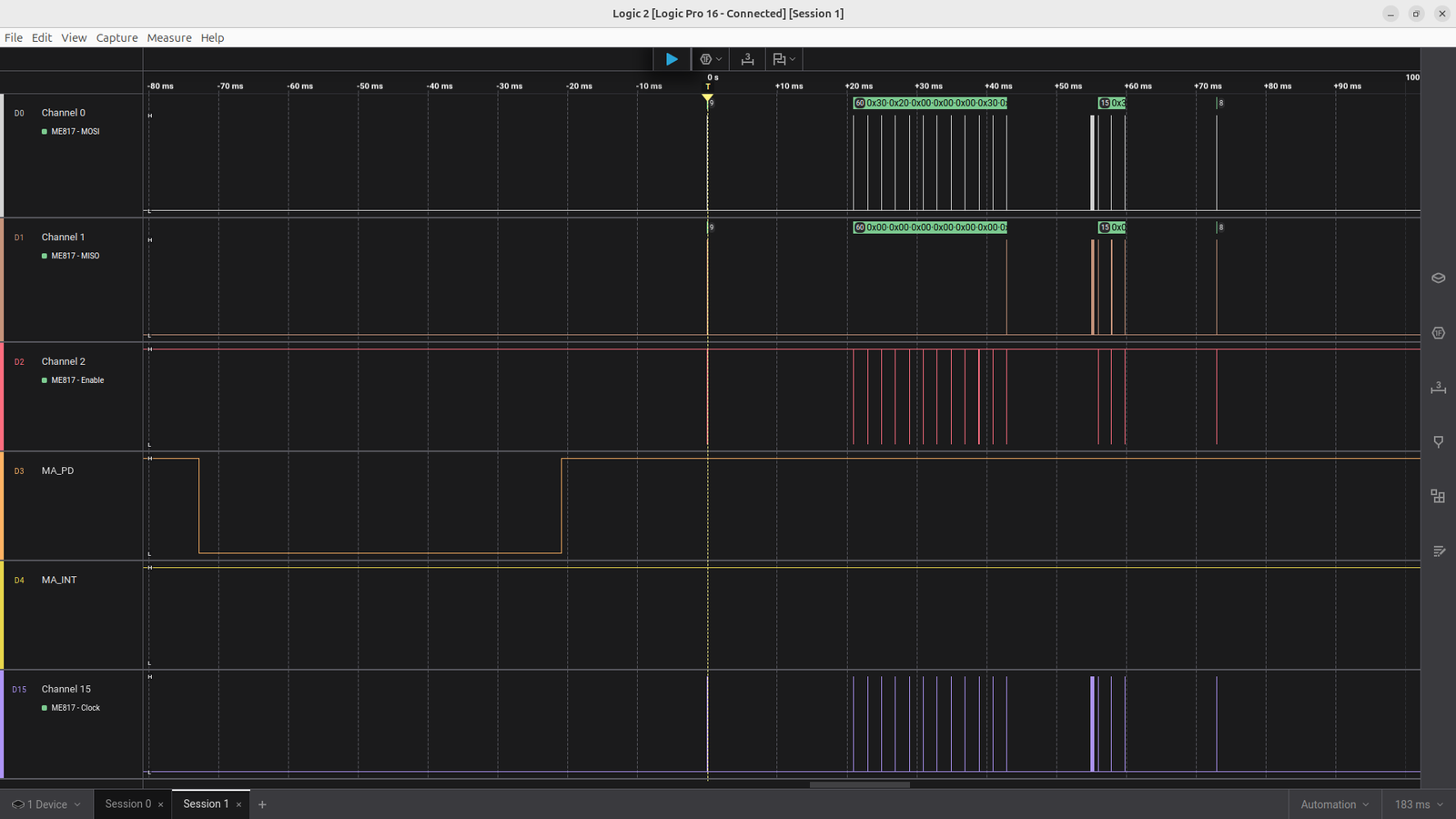
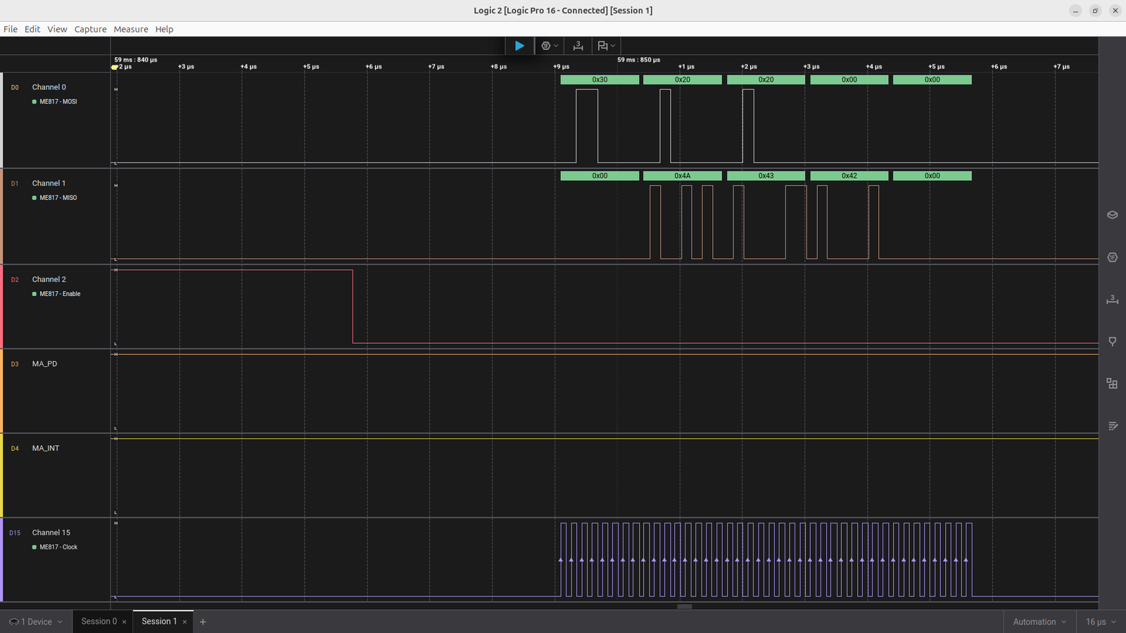
The host commands, three bytes each with CS# low around each one. While the STM32 sends the command, a live BT817 answers 0x00 0x4A 0x43 on MISO: a good sign that it is powered and wired, before a single register has been read.
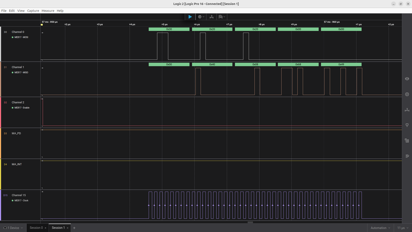
While the BT817 boots, REG_ID (address 0x302000, sent as 0x30 0x20 0x00, then the dummy byte) reads 0x00, and the check keeps polling:
Once it has booted, the same read returns 0x7C:
Next, REG_CPURESET (address 0x302020). The first reads come back non-zero while engines are still held in reset:
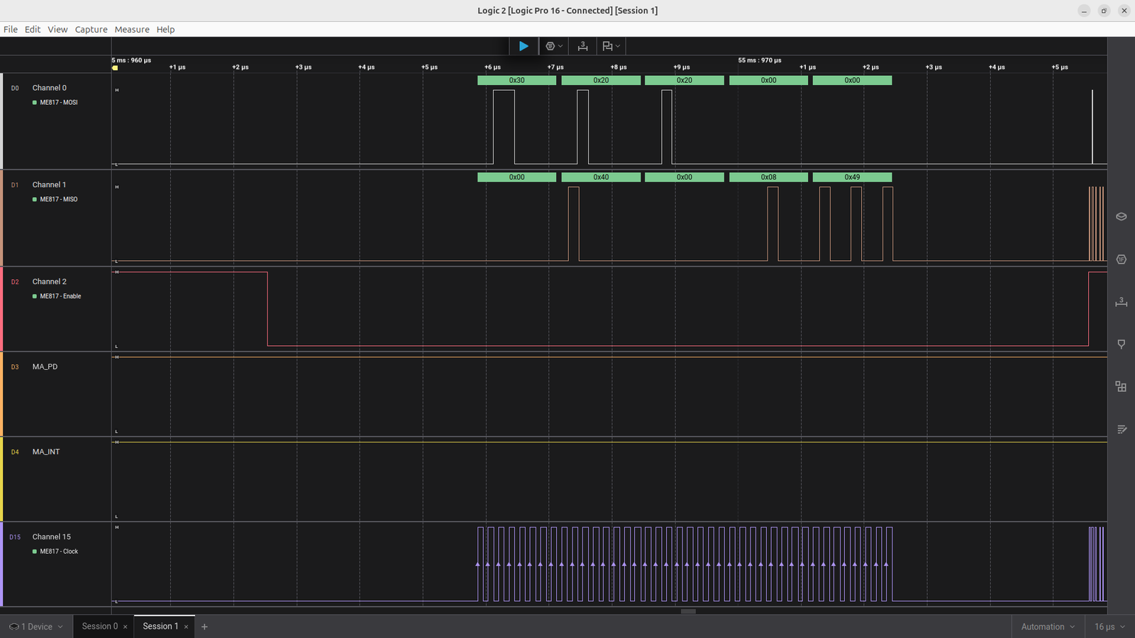
Until all three engines run and it reads 0x00:
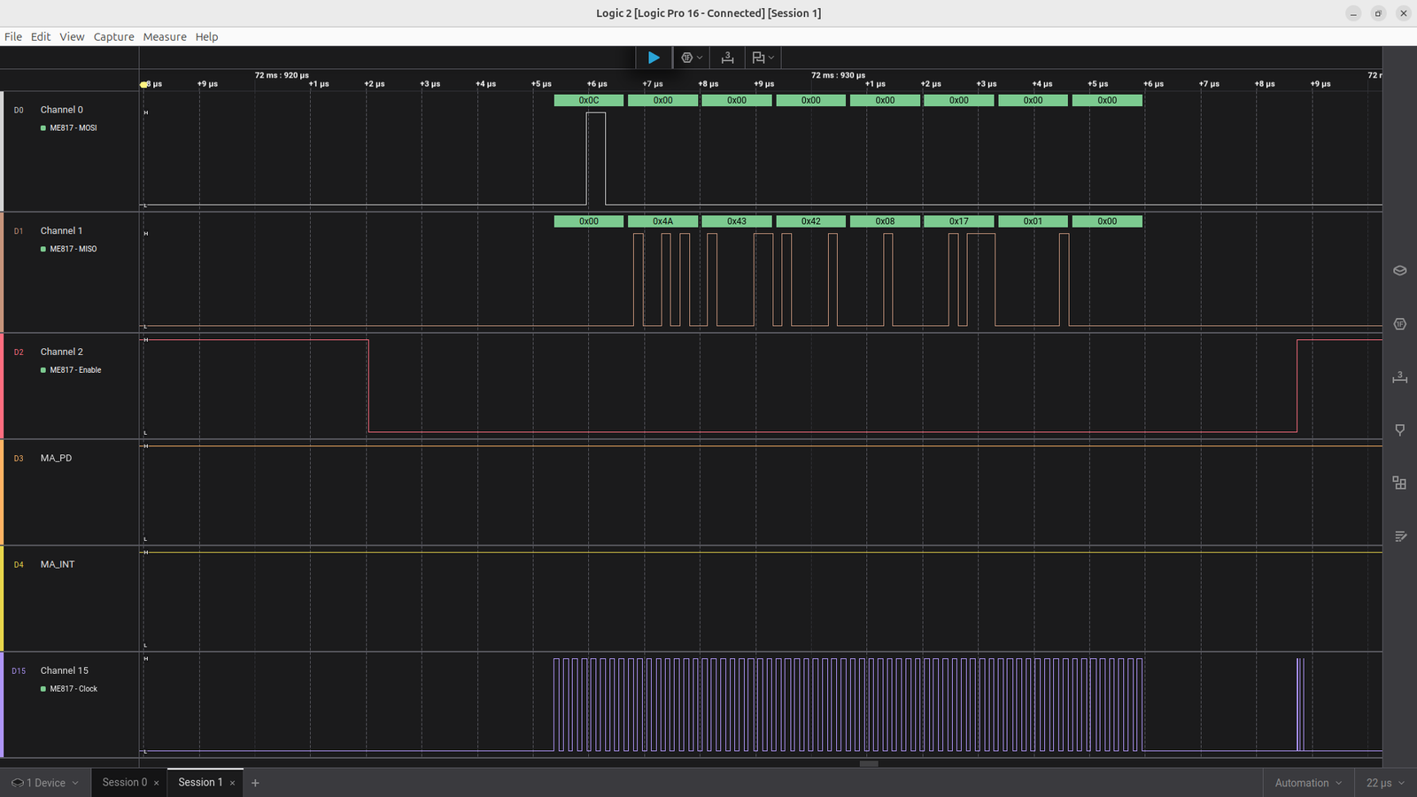
Finally the chip ID, four bytes from 0x0C0000:
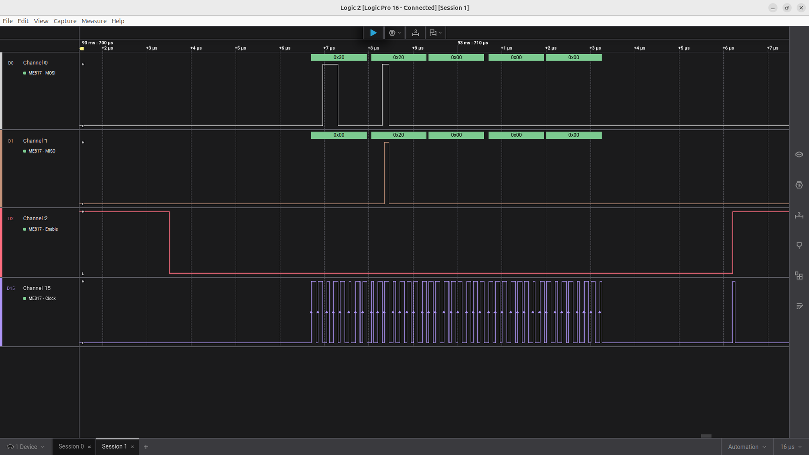
And this is the misplaced PD# wire from the troubleshooting section. The STM32 sends the REG_ID read, but the BT817 is still in power-down and nothing answers: MISO stays low apart from a short spike (crosstalk from the neighbouring line) and the data byte reads 0x00. A MISO line that never shows the 0x4A 0x43 answer during the address bytes points at the wiring or the ME817EV’s power and switches, not at the firmware.
Project Downloads
The complete project source code used in this tutorial is available for download. This includes all necessary files to build and run the project, along with supporting documentation.
- Full STM32CubeIDE Project (Source + Configuration), including Bridgetek’s demo in
EVE_Example/ - Doxygen Documentation (docs/html/index.html)
- Supporting Files: the STM32_Bridgetek_EVE_API library, as its own zip (see Getting the Library above)
Documentation
This project includes full Doxygen-generated documentation for all custom source files.
The documentation covers the project’s own code in main.c; Bridgetek’s library and demo are third-party code and are not part of it. It is included in the Doxygen documentation download above and can be viewed locally by opening:
H753_CPP_SPI_BT817_EVE_01/docs/html/index.htmlin a web browser.
The documentation provides detailed descriptions of functions, data structures, and module interactions to assist with understanding and extending the project.
What’s Next
With the hardware proven by Bridgetek’s own code, a future post will remove the vendor demo and draw our own screens in C with the same library: a button, a toggle, a slider with a gauge and a progress bar, a keypad, a clock and a dial, all driven by touch.
If you have questions or run into trouble getting the boards programmed and talking to each other, post in the Tutorial Support forum and I will work through it with you. If project source is not linked in the tutorial, it may be available on request — use the email contact option in the site footer.
Tutorials and code are provided as-is, without warranty. See the Disclaimer.