Overview
The STM32 RA8875 library tutorial shows how to drive Adafruit’s RA8875 driver board and 7-inch 800×480 TFT display from a NUCLEO-F439ZI over SPI, using two reusable HAL C++ libraries instead of a hand-converted copy of the Adafruit sources. STM32_GFX is a port of Adafruit GFX and STM32_RA8875 is a port of Adafruit_RA8875, with the same class names and the same public API, so Adafruit’s documentation and examples still apply.
This is the library-based successor to the earlier STM32 RA8875 TFT LCD tutorial. The wiring is simpler, because the chip-select and reset pins are handed to the library in its constructor and the WAIT and INT pins are not needed. The firmware runs the RA8875’s hardware drawing commands and its built-in text mode, and prints progress on a USART.
The same display family is used with a resistive touch controller in the STM32 resistive touch screen with the TSC2046 tutorial, which shares the same library style.
What You Will Learn
- How to wire the Adafruit RA8875 driver board and 7-inch display to an STM32 Nucleo board over SPI1 with only six signal wires
- How to add the STM32_GFX and STM32_RA8875 libraries to a CubeIDE project, with the include paths they need
- How the STM32 RA8875 library starts the controller: reset pulse, chip ID check (0x75) and the automatic SPI speed change
- How to reach the C++ display object from CubeMX’s plain-C main.c through
extern "C"entry points - How to run the RA8875 hardware drawing commands and text mode, and what to expect on the serial terminal
- Why the backlight does not dim with the PWM1 output on this board, and what the LITE pin is for
Prerequisites
You should be comfortable creating and building an STM32CubeIDE project and have a working knowledge of C and basic C++. Familiarity with SPI (clock, MOSI, MISO, chip-select) helps. Debug output is redirected to printf over USART1 through an external FTDI USB-to-serial adapter, per this site’s standard debug setup, and viewed in any serial terminal at 19200 baud.
Materials List
- NUCLEO-F439ZI
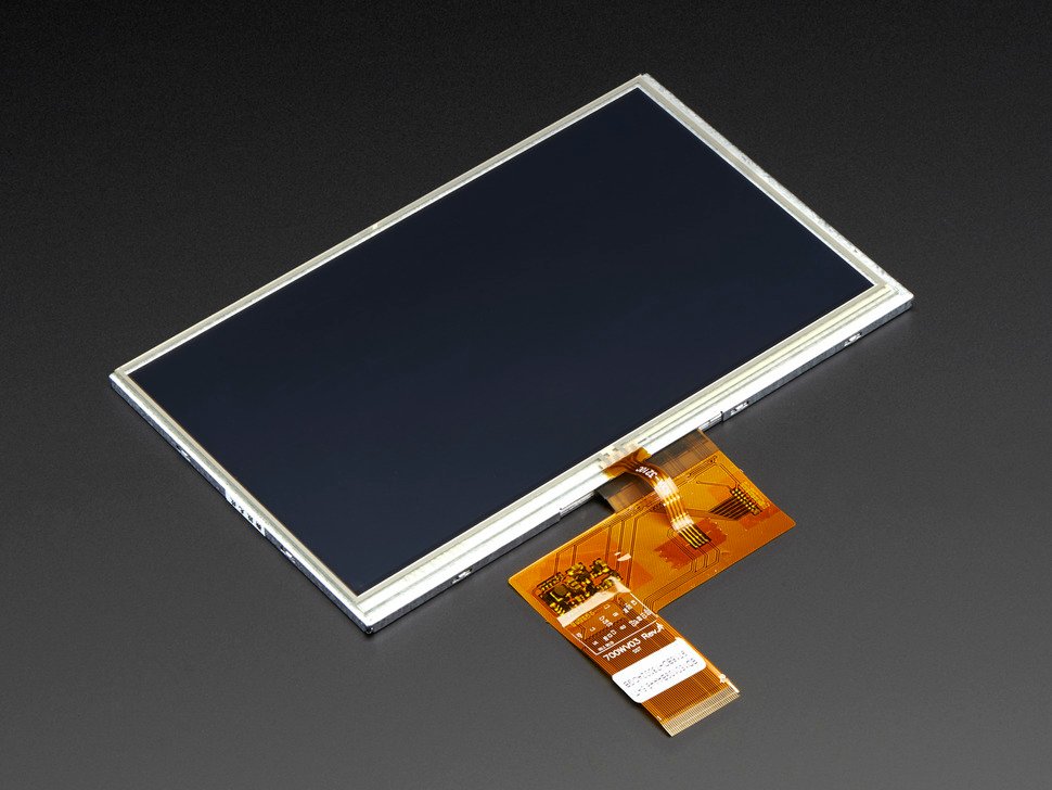
- RA8875 Driver Board for 40-pin TFT Touch Displays – 800×480 Max
- 7.0″ 40-pin TFT Display – 800×480 with Touchscreen
- FTDI to USB
- Breadboards Kit Include 2PCS 830 Point 2PCS 400 Point Solderless Breadboards
- Jumper wires and a USB cable for the Nucleo’s ST-LINK connector
Board Diagram
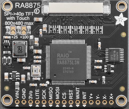
STM32 RA8875 Library: Driver Board and 7-Inch Display
The RA8875 is a display controller that drives panels up to 800×480 and adds hardware drawing (lines, rectangles, circles, ellipses, triangles, curves) and a built-in text mode, so the microcontroller sends short commands over SPI instead of every pixel. Adafruit’s driver board carries the RA8875 and the 40-pin connector for the display; the library uses SPI, a chip-select pin and a reset pin.
Project Structure
The project uses two reusable libraries that live in their own folders, STM32_GFX and STM32_RA8875. Each is a separate download (see Getting the Libraries below) so they can be shared with other projects. After you unpack the source zip and both library zips into one project folder the tree looks like this — the two library folders are marked:
F439_CPP_SPI_RA8875_TFT_LCD_03/
├── STM32_GFX/                   <- from the STM32_GFX zip
│   ├── Adafruit_GFX.cpp
│   ├── Adafruit_GFX.h
│   ├── Print.cpp
│   ├── Print.h
│   ├── STM32_Arduino_Compat.h
│   ├── WString.h
│   ├── gfxfont.h
│   ├── glcdfont.c
│   ├── Fonts/                   (Adafruit GFX font headers)
│   ├── LICENSE
│   └── README.md
├── STM32_RA8875/                <- from the STM32_RA8875 zip
│   ├── Adafruit_RA8875.cpp
│   ├── Adafruit_RA8875.h
│   ├── LICENSE
│   └── README.md
├── Core/
│   ├── Inc/
│   │   ├── main.h
│   │   └── entryPointCPP.hpp
│   └── Src/
│       ├── main.c
│       └── entryPointCPP.cpp
├── F439_CPP_SPI_RA8875_TFT_LCD_03.ioc
├── F439_CPP_SPI_RA8875_TFT_LCD_03.pdf
├── F439_CPP_SPI_RA8875_TFT_LCD_03.txt
├── LICENSE
├── README.md
├── STM32F439ZITX_FLASH.ld
└── STM32F439ZITX_RAM.ld
Hardware Configuration / Pinouts
Overview
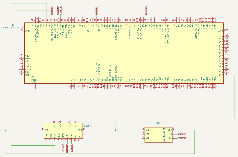
The STM32 RA8875 library talks SPI1 in standard full-duplex master mode (8-bit, clock polarity low, first clock edge, MSB first, software NSS). Chip-select and reset are plain GPIO outputs that you pass to the library’s constructor, so any two free pins work. On the breadboard the SPI pins were grouped on the CN12 header next to PA9/PA10 to keep the wiring short.
| RA8875 board | Nucleo-F439ZI Pin | Notes |
|---|---|---|
| Vin | +5V | Power |
| GND | GND | |
| SCK | PA5 | SPI1_SCK |
| MISO | PA6 | SPI1_MISO |
| MOSI | PA7 | SPI1_MOSI |
| CS | PB6 | GPIO output, label RA8875_CS, initial level high |
| Rst | PC7 | GPIO output, label LCD_RESET |
| Wait, Int, LITE, 3Vo | not connected | WAIT and INT are not used; LITE is the backlight dimming input (see below) |
| FTDI RX / TX | PA9 / PA10 | USART1_TX / USART1_RX, debug output at 19200 baud |
The display’s own touch panel connections (X+, X-, Y+, Y-) are not used in this tutorial.
FTDI Pinouts
FTDI to USB Pinout from right to left
- Pin 1 – GND
- Pin 4 – TX
- Pin 5 – RX
- USB Mini – Connect to PC via USB cable
Make sure the jumper is set to 5V — the FTDI board is powered from the USB mini cable, and a computer’s USB port supplies 5 V. The FTDI TX goes to the Nucleo’s PA10 (USART1_RX) and the FTDI RX to PA9 (USART1_TX).
If the schematic is too small to read clearly, open the full-size image in a new tab and use Ctrl-Scroll to zoom in.
Pinouts & Configurations
The complete CubeMX pin assignment and peripheral configuration is captured in the IOC report below.
Project Setup
Create a new STM32CubeIDE project for the STM32 RA8875 library tutorial, targeting the NUCLEO-F439ZI with C++ enabled (main.c itself stays plain C — see the Code Walkthrough). In the .ioc pinout view:
- Enable SPI1 in Full-Duplex Master mode on PA5/PA6/PA7, 8-bit data, clock polarity low, clock phase 1 edge (SPI mode 0), MSB first, NSS set to Disable (software). The baud-rate prescaler CubeMX shows (128) is only the starting value: the library changes it itself while the controller starts.
- Configure PB6 as a GPIO Output labeled
RA8875_CS, initial level high. - Configure PC7 as a GPIO Output labeled
LCD_RESET. - Enable USART1 in Asynchronous mode on PA9/PA10 at 19200 baud for the printf redirect.
Getting the Libraries
The source download contains only this project’s own files. The two libraries are shared code, so each is provided as its own download, just like its own repository. STM32_RA8875 builds on STM32_GFX, so you need both.
Create the CubeIDE project as described above, then extract the source zip over it (or copy the files from the zip into the matching folders). Let CubeIDE overwrite the files it generated.
- Extract both library zips (
STM32_GFX.zipandSTM32_RA8875.zip) into the project root (the folder that containsCore/). You should now haveSTM32_GFX/andSTM32_RA8875/next toCore/, exactly as in the Project Structure tree above. Each zip already contains its own folder name, so extract them “here” — do not create an extra subfolder. - In CubeIDE, right-click the project and choose Refresh (F5). The two new folders appear in the Project Explorer and are compiled automatically.
- Open Project → Properties → C/C++ Build → Settings. Under both MCU GCC Compiler → Include paths and MCU G++ Compiler → Include paths, add
${workspace_loc:/${ProjName}/STM32_GFX}and${workspace_loc:/${ProjName}/STM32_RA8875}. Do this for both the Debug and Release configurations. The code includes the library headers by plain name (for example#include "Adafruit_RA8875.h"), so these paths are what make them resolvable. - Build the project. If you see “Adafruit_RA8875.h: No such file or directory”, the include paths in step 3 are missing or were added to only one of the C/C++ compilers or one configuration.
The libraries are also maintained as separate repositories, STM32_GFX and STM32_RA8875. If you prefer git, clone them into the project root, or add them as submodules so each library keeps its own history. When you later clone a project that already uses them as submodules, run git clone --recurse-submodules <project-url> (or git submodule update --init after a plain clone).
Code Walkthrough
How the STM32 RA8875 Library Starts the Display
The firmware creates one Adafruit_RA8875 object with the SPI handle plus the CS and RESET port and pin, then calls begin(RA8875_800x480). Inside begin() the library sets CS high, pulses RESET low for 100 ms and releases it for another 100 ms, reads the chip ID register (it must be 0x75) and starts the SPI bus at its slowest prescaler (about 350 kHz from SPI1’s 90 MHz clock) while the controller’s PLL comes up. Once the PLL is running it raises the SPI clock to the fastest setting not above 4 MHz, which is 2.8 MHz on this board. If the chip ID is wrong, begin() returns false, which almost always means a wiring or SPI-setting mistake.
The optional WAIT pin is not wired and not used. The library only polls it if you pass its port and pin as the last two constructor arguments, and its wait loop has no timeout, so leave it out unless the pin is actually connected.
C/C++ bridge: entryPointCPP
CubeMX regenerates main.c as plain C every time the .ioc changes, so the C++ display object is reached through two C-callable functions declared extern "C". The object is created with new inside initTest(), called from main() after MX_SPI1_Init() — never as a global, because global constructors run before main() and before the clocks and SPI peripheral exist. See the STM32 C++ code integration post for the background on this pattern.
First the header, entryPointCPP.hpp:
/**
 * @file entryPointCPP.hpp
 * @project F439_CPP_SPI_RA8875_TFT_LCD_03
 * @brief  C-callable entry points into the C++ RA8875 display code.
 *
 * The CubeMX-generated main.c is plain C, so it cannot create or call the
 * C++ Adafruit_RA8875 object directly. This header declares the small set of
 * `extern "C"` functions that main.c calls instead; their bodies are in
 * entryPointCPP.cpp, which owns the display object.
 *
 *  Created on: Jan 26, 2025
 *      Author: johng
 */

#ifndef INC_ENTRYPOINTCPP_HPP_
#define INC_ENTRYPOINTCPP_HPP_


#include "main.h"

// Define all C function calls that will be called from main.c in the following extern "C" group
// Using extern "C" stops name mangling and allows "C" code to call C++ code

#ifdef __cplusplus
extern "C" {
#endif

/**
 * @brief  Creates the display object and starts the RA8875 controller.
 * @param  halSPI Handle of the SPI peripheral wired to the display (SPI1 here,
 *         set up by CubeMX as master, full duplex, 8-bit, mode 0, MSB first,
 *         software NSS).
 *
 * Constructs an Adafruit_RA8875 with the SPI handle and the CS
 * (RA8875_CS_*) and RESET (LCD_RESET_*) pins from main.h, then calls
 * Adafruit_RA8875::begin() for an 800x480 panel. begin() sets CS high, pulses
 * RESET, reads the chip ID (it must be 0x75), initialises the controller and
 * raises the SPI clock, so nothing else needs to be done here. Prints
 * "RA8875 Found" on the redirected USART; if the chip does not answer it
 * prints a message and calls Error_Handler(). The WAIT and INT pins are not
 * used.
 *
 * @note   Call it once from main.c, after the CubeMX `MX_..._Init()` calls,
 *         inside a USER CODE section. The object is created with `new` at this
 *         point, not as a global, so it is not constructed before the clocks
 *         and the SPI peripheral exist.
 * @warning Not thread-safe and not ISR-safe: it stores the new object in a
 *         shared global pointer without any lock, and begin() is a sequence of
 *         separate SPI transactions. A task switch (or an interrupt) that
 *         called testLCD() or any other display call in between would use a
 *         half-initialised display or interleave its SPI transfers with
 *         begin()'s. Call it once, from the main thread, before anything else
 *         touches the display.
 */
void initTest(SPI_HandleTypeDef *halSPI);

/**
 * @brief  Runs one of the two display demonstrations.
 * @param  buildTest `true` runs the graphics demo, `false` runs the text demo.
 *
 * The graphics demo turns the display on, enables the backlight output,
 * fills the screen with seven colours in turn, then draws a circle,
 * rectangles, a rounded rectangle, single pixels, a line, triangles, ellipses
 * and curves using the RA8875's hardware drawing commands. The text demo
 * clears the screen, switches to the controller's text mode and prints
 * "Hello, World!" in several foreground and background colours and four
 * enlargement sizes, with a blinking cursor. Progress is printed on the
 * redirected USART. If `PWM` is defined at build time, the graphics demo also
 * sweeps the PWM1 output down and up; it is compiled out by default because
 * on Adafruit's board PWM1 does not reach the backlight (see the
 * Adafruit_RA8875 documentation).
 *
 * @note   initTest() must have run first. If it has not, testLCD() prints an
 *         error and calls Error_Handler() instead of using a NULL display.
 * @warning Not thread-safe and not ISR-safe: every drawing call is several
 *         separate SPI transactions (set the cursor, then the colour, then the
 *         draw command), all on one shared display object. A task switch
 *         between two of them lets a second caller's commands interleave with
 *         the first caller's and corrupt both. Call it from one thread only,
 *         and never from an interrupt. The demos also block for several seconds
 *         in HAL_Delay().
 */
void testLCD(bool buildTest);

#ifdef __cplusplus
}
#endif


#endif /* INC_ENTRYPOINTCPP_HPP_ */Then entryPointCPP.cpp, which owns the display object. initTest() creates and starts it, and testLCD() runs the two demonstrations. Note the null check at the top of testLCD(): if initTest() has not run it fails loudly instead of using a null pointer. The PWM sweep is compiled out unless PWM is defined (see Backlight and PWM below).
/*
 * entryPointCPP.cpp
 *
 *  Created on: Jan 26, 2025
 *      Author: johng
 */

#include <stdio.h>
#include "entryPointCPP.hpp"
#include "Adafruit_RA8875.h"

/** The display object. NULL until initTest() has created it; shared by initTest() and testLCD(). */
Adafruit_RA8875 *tft = nullptr;

/*
 * Creates the display object and starts it. With the STM32_RA8875 library the
 * constructor takes the SPI handle plus the CS and RESET port/pin directly, and
 * begin() itself sets CS high, pulses RESET, reads the chip ID and raises the
 * SPI clock, so none of that is done here. WAIT and INT are not used.
 */
void initTest(SPI_HandleTypeDef *halSPI) {
	tft = new Adafruit_RA8875(halSPI, RA8875_CS_GPIO_Port, RA8875_CS_Pin,
			LCD_RESET_GPIO_Port, LCD_RESET_Pin);

	if (tft->begin(RA8875_800x480)) {
		printf("RA8875 Found\r\n");
	} else {
		printf("RA8875 not found (expected chip ID 0x75)\r\n");
		Error_Handler();
	}
}

void testLCD(bool buildTest) {
	if (tft == nullptr) {		// initTest() has not run yet; fail loudly instead of dereferencing NULL
		printf("ERROR: testLCD() called before initTest()\r\n");
		Error_Handler();
	}

	if (buildTest) {
		printf("================  Graphics Mode =============\r\n");

	  tft->displayOn(true);
	  HAL_Delay(1);
	  tft->GPIOX(true);
	  HAL_Delay(1);
	  tft->PWM1config(true, RA8875_PWM_CLK_DIV1024);
	  tft->PWM1out(255);
	  HAL_Delay(1);

	  tft->graphicsMode();

	  printf("FillSreen White\r\n");
	  tft->fillScreen(RA8875_WHITE);

	  HAL_Delay(1000);
#ifdef PWM
	  // Play with PWM
	  printf("Start: Play with PWM\r\n");

	  for (uint8_t i=255; i!=0; i-=5 )
	  {
		tft->PWM1out(i);
		delay(100);
	  }
	  for (uint8_t i=0; i!=255; i+=5 )
	  {
		tft->PWM1out(i);
		delay(100);
	  }
	  tft->PWM1out(255);

	  printf("END: Play with PWM\r\n");
	  HAL_Delay(2000);
#endif
	  printf("FillSreen Red\r\n");
	  tft->fillScreen(RA8875_RED);
	  HAL_Delay(1000);
	  printf("FillSreen Yellow\r\n");
	  tft->fillScreen(RA8875_YELLOW);
	  HAL_Delay(1000);
	  printf("FillSreen Green\r\n");
	  tft->fillScreen(RA8875_GREEN);
	  HAL_Delay(1000);
	  printf("FillSreen Cyan\r\n");
	  tft->fillScreen(RA8875_CYAN);
	  HAL_Delay(1000);
	  printf("FillSreen Magenta\r\n");
	  tft->fillScreen(RA8875_MAGENTA);
	  HAL_Delay(1000);
	  printf("FillSreen Black\r\n");
	  tft->fillScreen(RA8875_BLACK);
	  HAL_Delay(1000);

	  // Try some GFX acceleration!
	  printf("drawCircle\r\n");
	  tft->drawCircle(100, 100, 50, RA8875_BLACK);
	  printf("fillCircle\r\n");
	  tft->fillCircle(100, 100, 49, RA8875_GREEN);

	  HAL_Delay(1000);

	  printf("fillRect\r\n");
	  tft->fillRect(11, 11, 398, 198, RA8875_BLUE);
	  HAL_Delay(1000);
	  printf("drawRect\r\n");
	  tft->drawRect(10, 10, 400, 200, RA8875_GREEN);
	  HAL_Delay(1000);
	  printf("fillRoundRect\r\n");
	  tft->fillRoundRect(200, 10, 200, 100, 10, RA8875_RED);
	  HAL_Delay(1000);
	  printf("drawPixel\r\n");
	  tft->drawPixel(10,10,RA8875_BLACK);
	  HAL_Delay(1000);
	  printf("drawPixel\r\n");
	  tft->drawPixel(11,11,RA8875_BLACK);
	  HAL_Delay(1000);
	  printf("drawLine\r\n");
	  tft->drawLine(10, 10, 200, 100, RA8875_RED);
	  HAL_Delay(1000);
	  printf("drawTriangle\r\n");
	  tft->drawTriangle(200, 15, 250, 100, 150, 125, RA8875_BLACK);
	  HAL_Delay(1000);
	  printf("fillTriangle\r\n");
	  tft->fillTriangle(200, 16, 249, 99, 151, 124, RA8875_YELLOW);
	  HAL_Delay(1000);
	  printf("drawEllipse\r\n");
	  tft->drawEllipse(300, 100, 100, 40, RA8875_BLACK);
	  HAL_Delay(1000);
	  printf("fillEllipse\r\n");
	  tft->fillEllipse(300, 100, 98, 38, RA8875_GREEN);
	  HAL_Delay(1000);
	  // Argument 5 (curvePart) is a 2-bit value to control each corner (select 0, 1, 2, or 3)
	  printf("drawCurve\r\n");
	  tft->drawCurve(50, 100, 80, 40, 2, RA8875_BLACK);
	  HAL_Delay(1000);
	  printf("fillCurve\r\n");
	  tft->fillCurve(50, 100, 78, 38, 2, RA8875_WHITE);
	} else {
		printf("================  Text Mode =============\r\n");
	  tft->displayOn(true);
	  tft->GPIOX(true);      // Enable TFT - display enable tied to GPIOX
	  tft->PWM1config(true, RA8875_PWM_CLK_DIV1024); // PWM output for backlight
	  tft->PWM1out(255);
	  printf("fillScreen\r\n");
	  tft->fillScreen(RA8875_BLACK);

	  /* Switch to text mode */
	  tft->textMode();
	  tft->cursorBlink(32);


	  /* Set a solid for + bg color ... */

	  /* ... or a fore color plus a transparent background */


	  /* Set the cursor location (in pixels) */
	  tft->textSetCursor(10, 10);

	  /* Render some text! */
	  printf("Render lots of Texts\r\n");
	  char string[80] = "Hello, World! ";
	  tft->textTransparent(RA8875_WHITE);
	  tft->textWrite(string);
	  HAL_Delay(500);
	  tft->textColor(RA8875_WHITE, RA8875_RED);
	  tft->textWrite(string);
	  HAL_Delay(500);
	  tft->textTransparent(RA8875_CYAN);
	  tft->textWrite(string);
	  HAL_Delay(500);
	  tft->textTransparent(RA8875_GREEN);
	  tft->textWrite(string);
	  HAL_Delay(500);
	  tft->textColor(RA8875_YELLOW, RA8875_CYAN);
	  tft->textWrite(string);
	  HAL_Delay(500);
	  tft->textColor(RA8875_BLACK, RA8875_MAGENTA);
	  tft->textWrite(string);

	  HAL_Delay(1000);

	  tft->textSetCursor(100, 100);
	  tft->textEnlarge(1);
	  tft->textTransparent(RA8875_YELLOW);
	  tft->textWrite(string);

	  tft->textSetCursor(100, 150);
	  tft->textEnlarge(2);
	  tft->textTransparent(RA8875_YELLOW);
	  tft->textWrite(string);

	  tft->textSetCursor(100, 200);
	  tft->textEnlarge(3);
	  tft->textTransparent(RA8875_YELLOW);
	  tft->textWrite(string);

	  tft->textSetCursor(100, 300);
	  tft->textEnlarge(0);
	  tft->textTransparent(RA8875_YELLOW);
	  tft->textWrite(string);
	}
}main.c
Everything below lives inside the CubeMX USER CODE blocks, so regenerating the project does not remove it. First the include, then the startup sequence after the peripherals are initialised:
#include <stdio.h>
#include "string.h"
#include "stdbool.h"
#include "entryPointCPP.hpp"
  printf("\x1b[2J\x1b[H");	// Clear the dumb terminal screen
  printf("Starting Initialization Process\r\n");

  initTest(&hspi1);

HAL_Delay(500);Then the main loop, which runs the graphics demo, pauses, runs the text demo and repeats:
  while (1)
  {
	  printf("Start Tests\r\n");
	  testLCD(true);
	  HAL_Delay(5000);
	  testLCD(false);
	  printf("Done\r\n");
HAL_Delay(5000);Backlight and PWM
The PWM1config() and PWM1out() calls control the RA8875 chip’s own PWM1 output, and Adafruit’s examples comment them as “PWM output for backlight”. On Adafruit’s driver board, however, the backlight is controlled through the board’s separate LITE pin. With LITE unconnected the backlight simply stays on, and sweeping PWM1 changes nothing you can see, which is what happened on this breadboard. The sweep in testLCD() is therefore wrapped in #ifdef PWM and compiled out by default. To dim the backlight, drive LITE yourself, for example from a timer PWM output, after checking the board’s schematic for its input voltage.
Things to Know
- No SPI error checking. The library does not check the HAL return codes of its SPI transfers, so a failed transfer shows up as a blank or garbled display. The chip ID check in
begin()catches most wiring and SPI-setting mistakes at start-up. - Not thread-safe. One display object is shared by the demo functions, and each drawing call is several separate SPI transactions, so call the display from one thread only and never from an interrupt.
- Milliseconds. The libraries use Adafruit’s millisecond
delay()(HAL_Delay), so the reset pulse and the other waits last as long as Adafruit intended.
Running It
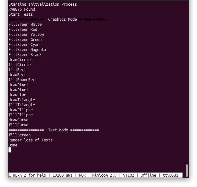
Open a serial terminal at 19200 baud and reset the board. The display runs the graphics demo (seven full-screen colors, then circles, rectangles, a rounded rectangle, pixels, a line, triangles, ellipses and curves), pauses, runs the text demo (“Hello, World!” in several colors and four sizes with a blinking cursor), and repeats. The terminal shows each step as it runs:
The video below shows the same demo running. It was recorded with the earlier version of this project, so the code differs, but the screens you should see are the same. Delays in the demo code let you watch each step; without them the whole demo would finish in under 15 seconds.
Project Downloads
The complete STM32 RA8875 library project used in this tutorial is available for download in four parts. The source download contains this project’s own files; the two library downloads, STM32_GFX and STM32_RA8875, go into the project root (see Getting the Libraries above).
- Project source: Core/ sources, IOC file and IOC report, README, LICENSE, linker scripts
- Libraries: STM32_GFX (
STM32_GFX/) and STM32_RA8875 (STM32_RA8875/), one zip each - Doxygen documentation (docs/html/index.html)
Documentation
The Doxygen documentation covers the project source and both libraries, so index.html covers everything. It is a separate download above and is not needed to build the project; extract it and open:
F439_CPP_SPI_RA8875_TFT_LCD_03/docs/html/index.htmlin a web browser.
If you have questions or run into trouble getting the boards programmed and talking to each other, post in the Tutorial Support forum and I will work through it with you. If project source is not linked in the tutorial, it may be available on request — use the email contact option in the site footer.