Overview
This STM32 FRAM touch calibration tutorial adds the touch panel of the Adafruit RA8875 driver board and 7-inch display to a NUCLEO-F439ZI, runs a three-point calibration from the serial terminal, and stores the result in an Adafruit MB85RS64V SPI FRAM. On every later boot the firmware reads the calibration back from the FRAM, checks it, and reports it, so the touch panel never has to be calibrated again after a reset or a power cycle.
It is part 4 of the RA8875 series. Part 3 introduced the STM32_GFX and STM32_RA8875 libraries and drew on the display. This part adds a third library, STM32_MB85RS64V, an FRAM driver written for this series, and shares SPI1 between the display and the FRAM, each with its own chip-select pin. If you want the stand-alone FRAM story first, the older STM32 SPI FRAM tutorial covers the chip on its own, and the resistive touch screen tutorial covers a different touch controller.
- Overview
- What You Will Learn
- Prerequisites
- Materials List
- Board Diagram
- Adafruit SPI FRAM Breakout: MB85RS64V
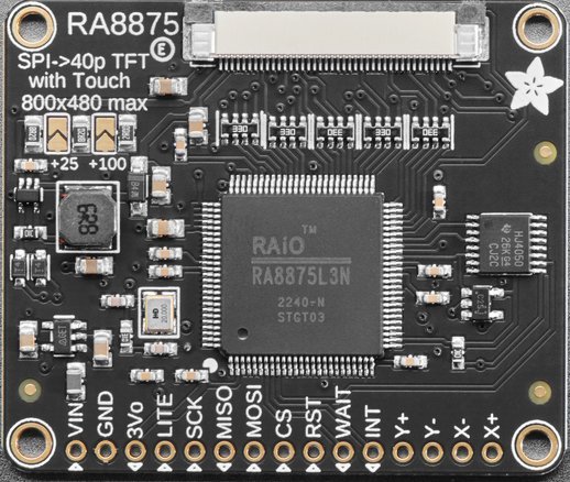
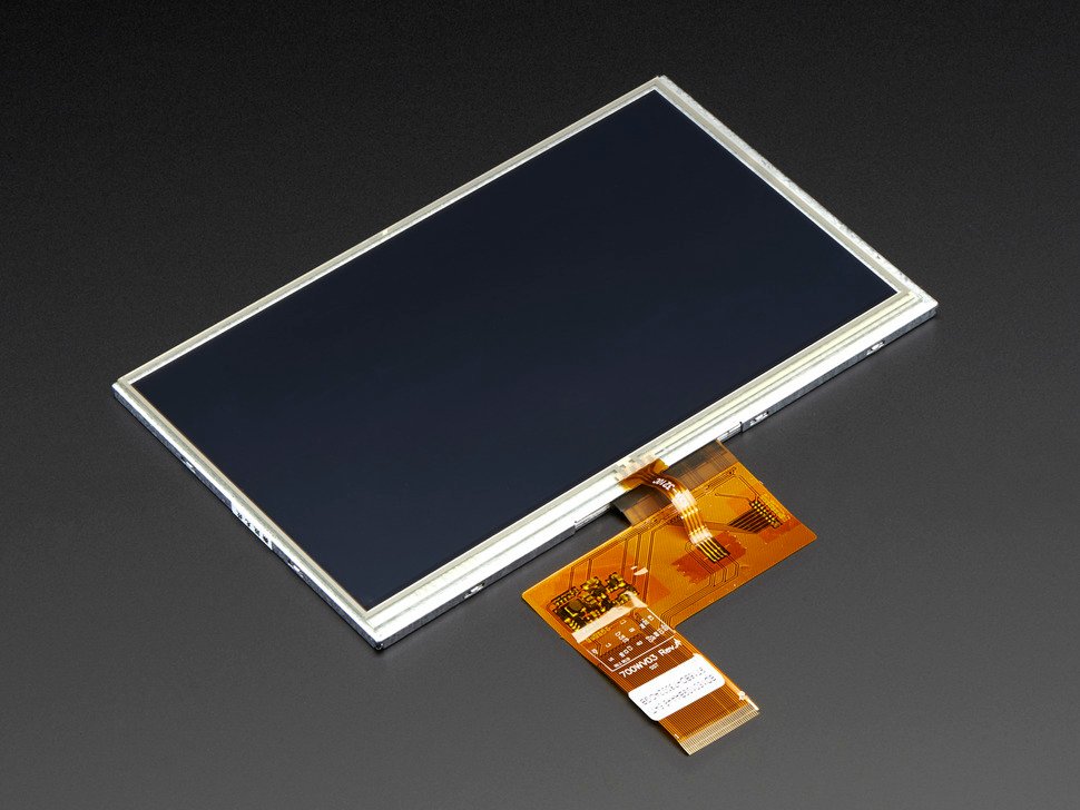
- RA8875 Driver Board and 7-Inch Display
- Project Structure
- Hardware Configuration / Pinouts
- Project Setup
- Code Walkthrough
- Running It: STM32 FRAM Touch Calibration on the Board
- Project Downloads
- Documentation
What You Will Learn
- How to share one SPI bus between an RA8875 display and an MB85RS64V FRAM, each with its own chip-select pin
- How the MB85RS64V FRAM driver identifies the chip, retries transient SPI failures and reports faults
- How to run a three-point calibration of the RA8875 resistive touch panel, with a press-and-hold capture that averages the readings
- How to advance the calibration from the serial terminal with the space bar, redo a point with Esc, and receive those keys with a UART interrupt and
HAL_UART_RxCpltCallback - How to store the calibration matrix in the FRAM with a header and a CRC-32 so that a damaged or half-written copy is never used
- How to read the stored calibration back at every boot, and how to switch between calibration mode and normal mode with one macro
Prerequisites
You should be comfortable creating and building an STM32CubeIDE project and have a working knowledge of C and basic C++. Familiarity with SPI (clock, MOSI, MISO, chip-select) helps, and this STM32 FRAM touch calibration tutorial builds directly on part 3, so reading it first is worthwhile. Debug output is redirected to printf over USART1 through an external FTDI USB-to-serial adapter, per this site’s standard debug setup, and viewed in any serial terminal at 19200 baud. The same terminal is used to answer the calibration prompts, so it must be able to send keystrokes.
Materials List
- NUCLEO-F439ZI
- RA8875 Driver Board for 40-pin TFT Touch Displays – 800×480 Max
- 7.0″ 40-pin TFT Display – 800×480 with Touchscreen
- Adafruit SPI Non-Volatile FRAM Breakout – 64Kbit / 8KByte
- FTDI to USB
- Breadboards Kit Include 2PCS 830 Point 2PCS 400 Point Solderless Breadboards
- Jumper wires and a USB cable for the Nucleo’s ST-LINK connector
Board Diagram
Adafruit SPI FRAM Breakout: MB85RS64V
FRAM (ferroelectric RAM) keeps its contents without power, like flash, but writes at bus speed with no erase step, no page buffer and no write delay, and it endures about 1012 writes per byte. That makes it a good place for a small value such as a calibration matrix: the write finishes when the SPI transfer does, and there is no wear to plan around. The MB85RS64V holds 64 Kbit (8192 bytes) and talks SPI mode 0 or 3 at up to 20 MHz. The Adafruit breakout brings out VCC, GND, HOLD, SCK, MISO, MOSI, CS and WP.
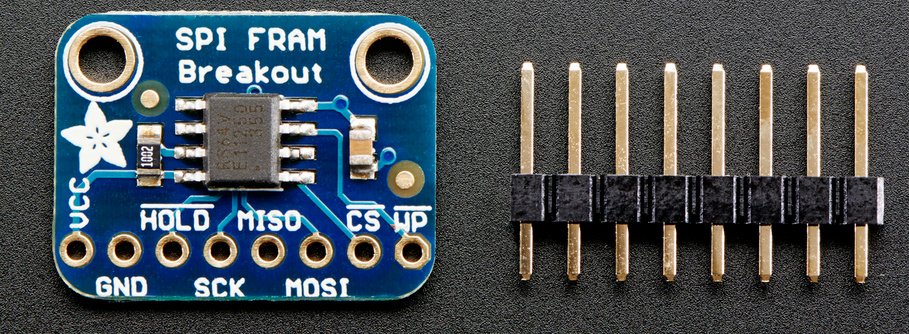
The chip’s HOLD input is active low and pauses the chip while it is low, so it must be tied high or the chip will not answer. WP is also active low and only protects the status register; tie it high as well. The MB85RS64V on this breakout is the newer, faster “V” part, and this tutorial’s driver is written for it (device ID 04 7F 03 02).
RA8875 Driver Board and 7-Inch Display
The display hardware is unchanged from part 3. The RA8875 drives the 800×480 panel and also contains the controller for the display’s four-wire resistive touch overlay: the touch panel is wired to the driver board through the display’s ribbon cable, so it needs no extra connections to the Nucleo.
Project Structure
The project uses three reusable libraries that live in their own folders: STM32_GFX, STM32_RA8875 and the new STM32_MB85RS64V. Each is a separate download (see Getting the Libraries below) so it can be shared with other projects. After you unpack the source zip and the three library zips into one project folder the tree looks like this, with the library folders marked:
F439_CPP_SPI_RA8875_TFT_LCD_04/
├── STM32_GFX/                   <- from the STM32_GFX zip
│   ├── Adafruit_GFX.cpp
│   ├── Adafruit_GFX.h
│   ├── Print.cpp
│   ├── Print.h
│   ├── STM32_Arduino_Compat.h
│   ├── WString.h
│   ├── gfxfont.h
│   ├── glcdfont.c
│   ├── Fonts/                   (Adafruit GFX font headers)
│   ├── LICENSE
│   └── README.md
├── STM32_RA8875/                <- from the STM32_RA8875 zip
│   ├── Adafruit_RA8875.cpp
│   ├── Adafruit_RA8875.h
│   ├── LICENSE
│   └── README.md
├── STM32_MB85RS64V/             <- from the STM32_MB85RS64V zip
│   ├── MB85RS64V.cpp
│   ├── MB85RS64V.hpp
│   ├── LICENSE
│   └── README.md
├── Core/
│   ├── Inc/
│   │   ├── main.h
│   │   ├── entryPointCPP.hpp
│   │   ├── touchCalibration.hpp
│   │   └── touchCalibrationStorage.hpp
│   └── Src/
│       ├── main.c
│       ├── entryPointCPP.cpp
│       ├── touchCalibration.cpp
│       └── touchCalibrationStorage.cpp
├── F439_CPP_SPI_RA8875_TFT_LCD_04.ioc
├── F439_CPP_SPI_RA8875_TFT_LCD_04.pdf
├── F439_CPP_SPI_RA8875_TFT_LCD_04.txt
├── LICENSE
├── README.md
├── STM32F439ZITX_FLASH.ld
└── STM32F439ZITX_RAM.ld
Hardware Configuration / Pinouts
Overview
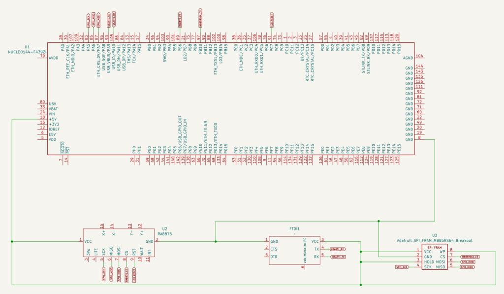
The STM32 FRAM touch calibration needs two SPI devices on one bus. The display and the FRAM share SPI1: SCK, MISO and MOSI go to both devices, and each device has its own chip-select pin, so only one of them listens at a time. SPI1 runs in standard full-duplex master mode (8-bit, clock polarity low, first clock edge, MSB first, software NSS), which both devices accept. Both chip-select pins are GPIO outputs whose initial level is set to high with a pull-up in CubeMX, so both devices are deselected from reset on.
| Signal | Nucleo-F439ZI Pin | Notes |
|---|---|---|
| SCK (display and FRAM) | PA5 | SPI1_SCK, shared |
| MISO (display and FRAM) | PA6 | SPI1_MISO, shared |
| MOSI (display and FRAM) | PA7 | SPI1_MOSI, shared |
| RA8875 CS | PB6 | GPIO output, label RA8875_CS, initial level high, pull-up |
| RA8875 Rst | PC7 | GPIO output, label LCD_RESET |
| MB85RS64V CS | PB10 | GPIO output, label MB85RS64_CS, initial level high, pull-up |
| MB85RS64V VCC | +5V | The chip takes 3.0 to 5.5 V. See the note below the table about its input levels |
| MB85RS64V GND | GND | |
| MB85RS64V HOLD | VCC (+5V) | Active low: a low level pauses the chip, so it will not answer |
| MB85RS64V WP | VCC (+5V) | Active low: only protects the status register; keep high so it stays writable |
| RA8875 Vin / GND | +5V / GND | Power for the driver board |
| FTDI RX / TX | PA9 / PA10 | USART1_TX / USART1_RX, debug output and calibration keys at 19200 baud |
The FRAM is powered from +5V here. Its high input level is 0.8 x VDD, which is 4.0 V at 5 V, while the STM32 drives its outputs to 3.3 V, so SCK, MOSI and CS are below the datasheet’s input level. It works on this breadboard, but powering the chip from 3.3 V instead puts those signals inside the specification.
The RA8875 board’s Wait, Int and LITE pins are not connected. Do not connect 3Vo. It is an output: the 3.3 V that the board’s own regulator produces. It is not a power input, so never wire it to VCC, to the Nucleo’s 3.3 V pin or to any other supply rail. The board is powered from Vin (+5V, see part 3).
FTDI Pinouts
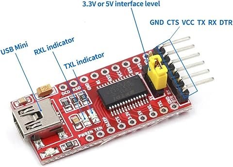
FTDI to USB Pinout from right to left
- Pin 1 – GND
- Pin 4 – TX
- Pin 5 – RX
- USB Mini – Connect to PC via USB cable
Make sure the jumper is set to 5V — the FTDI board is powered from the USB mini cable, and a computer’s USB port supplies 5 V. The FTDI TX goes to the Nucleo’s PA10 (USART1_RX) and the FTDI RX to PA9 (USART1_TX).
Schematic
If the schematic is too small to read clearly, open the full-size image in a new tab and use Ctrl-Scroll to zoom in. A vector (SVG) version is also available.
Pinouts & Configurations
The complete CubeMX pin assignment and peripheral configuration is captured in the IOC report below.
Project Setup
Create a new STM32CubeIDE project for the STM32 FRAM touch calibration, targeting the NUCLEO-F439ZI with C++ enabled (main.c itself stays plain C, see the Code Walkthrough). In the .ioc pinout view:
- Enable SPI1 in Full-Duplex Master mode on PA5/PA6/PA7, 8-bit data, clock polarity low, clock phase 1 edge (SPI mode 0), MSB first, NSS set to Disable (software). The baud-rate prescaler CubeMX shows is only a starting value: the display library changes it while the controller starts.
- Configure PB6 as a GPIO Output labeled
RA8875_CSand PB10 as a GPIO Output labeledMB85RS64_CS. For both, set the initial output level to High and the pull-up to Pull-up, so neither device is selected at reset. - Configure PC7 as a GPIO Output labeled
LCD_RESET. - Enable USART1 in Asynchronous mode on PA9/PA10 at 19200 baud for the printf redirect.
- Enable the USART1 global interrupt (USART1 → NVIC Settings → USART1 global interrupt). The space bar and Esc keys are received by interrupt, so without this setting the calibration prompt never sees a key.
Getting the Libraries
The source download contains only this project’s own files. The three libraries are shared code, so each is provided as its own download, just like its own repository. STM32_RA8875 builds on STM32_GFX, and the project also needs STM32_MB85RS64V, so the STM32 FRAM touch calibration project needs all three.
Create the CubeIDE project as described above, then extract the source zip over it (or copy the files from the zip into the matching folders). Let CubeIDE overwrite the files it generated.
- Extract the three library zips (
STM32_GFX_04.zip,STM32_RA8875_04.zipandSTM32_MB85RS64V.zip) into the project root (the folder that containsCore/). You should now haveSTM32_GFX/,STM32_RA8875/andSTM32_MB85RS64V/next toCore/, exactly as in the Project Structure tree above. Each zip already contains its own folder name, so extract it “here” — do not create an extra subfolder. - In CubeIDE, right-click the project and choose Refresh (F5). The new folders appear in the Project Explorer and are compiled automatically.
- Open Project → Properties → C/C++ Build → Settings. Under both MCU GCC Compiler → Include paths and MCU G++ Compiler → Include paths, add
${workspace_loc:/${ProjName}/STM32_GFX},${workspace_loc:/${ProjName}/STM32_RA8875}and${workspace_loc:/${ProjName}/STM32_MB85RS64V}. Do this for both the Debug and Release configurations. The code includes the library headers by plain name (for example#include "MB85RS64V.hpp"), so these paths are what make them resolvable. - Build the project. If you see “MB85RS64V.hpp: No such file or directory” (or the same for Adafruit_RA8875.h), the include paths in step 3 are missing or were added to only one of the C/C++ compilers or one configuration.
The libraries are also maintained as separate repositories, STM32_GFX, STM32_RA8875 and STM32_MB85RS64V. If you prefer git, clone them into the project root, or add them as submodules so each library keeps its own history. When you later clone a project that already uses them as submodules, run git clone --recurse-submodules <project-url> (or git submodule update --init after a plain clone).
Code Walkthrough
How the STM32 FRAM Touch Calibration Fits Together
Four pieces cooperate, and each lives in its own file:
MB85RS64V(library): the FRAM driver. It checks the SPI setup and the chip ID, reads and writes bytes, and retries a transient SPI failure before it callsError_Handler().touchCalibration.cpp: the interactive three-point calibration and the maths that turns raw touch readings into display coordinates.touchCalibrationStorage.cpp: saves the calibration matrix in the FRAM with a validity header, and loads and checks it again.entryPointCPP.cppandmain.c: the C/C++ bridge, the start-up sequence and the UART key callbacks.
The MB85RS64V Driver
The driver behind the STM32 FRAM touch calibration is an ordinary C++ class with an SPI handle and a chip-select port and pin passed to its constructor, in the same style as the display library. begin() checks that the SPI handle is set up the way the chip needs (master, 8-bit, MSB first, software NSS, mode 0 or 3) and that the device ID reads 04 7F 03 02, then leaves writes disabled. read() and write() take an address from 0x0000 to 0x1FFF; write() sends the write-enable command first, because the chip clears its write latch after every write.
A failed SPI call is handled in two steps. A transient failure (busy, timeout, or an SPI error such as an overrun) is retried: chip-select is released and the whole command is sent again, up to three attempts. Anything a retry cannot fix, such as a bad parameter, is not retried. When the attempts run out, or at once for an unfixable failure, the driver calls Error_Handler(), which does not return. The driver’s Doxygen documents this, and also that it is neither thread-safe nor ISR-safe: each operation is several separate SPI steps, and a second caller interleaving between them would corrupt both. The full documentation is in the docs download at the end of this post.
C/C++ Bridge: entryPointCPP
As in part 3, CubeMX regenerates main.c as plain C, so the C++ objects are reached through C-callable functions declared extern "C". The objects are created with new inside the init functions, called from main() after MX_SPI1_Init(), never as globals, because global constructors run before main() and before the clocks and SPI peripheral exist. See the STM32 C++ code integration post for the background on this pattern. First the header, entryPointCPP.hpp:
/**
 * @file entryPointCPP.hpp
 * @project F439_CPP_SPI_RA8875_TFT_LCD_04
 * @brief  C-callable entry points into the C++ RA8875 display code.
 *
 * The CubeMX-generated main.c is plain C, so it cannot create or call the
 * C++ Adafruit_RA8875 object directly. This header declares the small set of
 * `extern "C"` functions that main.c calls instead; their bodies are in
 * entryPointCPP.cpp, which owns the display object.
 *
 *  Created on: Jan 26, 2025
 *      Author: johng
 */

#ifndef INC_ENTRYPOINTCPP_HPP_
#define INC_ENTRYPOINTCPP_HPP_


#include "main.h"
#include <stdbool.h>

// Define all C function calls that will be called from main.c in the following extern "C" group
// Using extern "C" stops name mangling and allows "C" code to call C++ code

#ifdef __cplusplus
extern "C" {
#endif

void initTest(SPI_HandleTypeDef *halSPI);

void testLCD(bool buildTest);

void initFRAM(SPI_HandleTypeDef *halSPI);

void testFRAM(void);

bool initTouchCalibration(void);

#ifdef TOUCH_CALIBRATION_ENABLE
/**
 * @brief  Enables touch, runs the three-point calibration and shows the result.
 *
 * Switches the display and its backlight on, enables the RA8875's touch panel, then runs the interactive calibration
 * (three targets, touched one at a time) and prints the raw and display
 * coordinates of each target on the redirected USART. Afterwards it clears the
 * screen and, for about 15 seconds, draws a small red dot wherever the screen
 * is touched, using the calibrated position, and prints the raw and calibrated
 * coordinates of each touch.
 *
 * This is calibration mode: it always runs the interactive calibration, ignores
 * whatever calibration the FRAM already holds, and overwrites it with the new
 * matrix (see touchCalibrationStorage.hpp), which is read back to check it. If the display or FRAM
 * object does not exist, the calibration fails after repeated attempts, or the
 * stored copy does not read back correctly, it prints the reason and calls
 * Error_Handler(), which does not return.
 *
 * @param  huart UART handle of the serial terminal (USART1); the calibration asks for the space bar
 *         on it between the targets, so the terminal must be open and able to send keys.
 *
 * @note   initTest() and initFRAM() must have run first. Call it from main.c inside a USER CODE section.
 * @warning Not thread-safe and not ISR-safe: it uses the one shared display
 *         object, and every drawing and touch call is several separate SPI
 *         transactions on a bus shared with the FRAM driver, so a task switch
 *         or interrupt that used the display or the FRAM in between could
 *         interleave its transfers and corrupt both. Call it from one thread
 *         only, while nothing else uses SPI1. It blocks until the user has
 *         touched all three targets.
 */
void testTouch(UART_HandleTypeDef *huart);
#endif /* TOUCH_CALIBRATION_ENABLE */

#ifdef __cplusplus
}
#endif


#endif /* INC_ENTRYPOINTCPP_HPP_ */Then entryPointCPP.cpp. initTest() and testLCD() are the display functions from part 3. initFRAM() creates the FRAM driver after the display is up, because the FRAM shares SPI1 with it: the display library has then left the bus in settings the FRAM also accepts. It checks the ID read twice, and retries a wrong or failed read up to three times before it fails, because a transfer can complete without error and still return wrong bytes. testFRAM() shows that the FRAM keeps its data: it prints the 16 bytes at address 0 that the previous run left, writes a pattern whose first byte is a boot counter, and reads it back. initTouchCalibration() reads the stored STM32 FRAM touch calibration data at every boot. testTouch() exists only in calibration mode.
/*
 * entryPointCPP.cpp
 *
 *  Created on: Jan 26, 2025
 *      Author: johng
 */

#include <stdio.h>
#include <string.h>
#include <new>
#include "entryPointCPP.hpp"
#include "Adafruit_RA8875.h"
#include "MB85RS64V.hpp"
#include "touchCalibrationStorage.hpp"
#ifdef TOUCH_CALIBRATION_ENABLE
#include "touchCalibration.hpp"
#endif

/** The display object. NULL until initTest() has created it; shared by initTest() and testLCD(). */
Adafruit_RA8875 *tft = nullptr;

/** The FRAM object. NULL until initFRAM() has created it; shared by initFRAM() and testFRAM(). */
static MB85RS64V *fram = nullptr;

/** The touch calibration read from the FRAM by initTouchCalibration(); only valid when touchMatrixValid is true. */
static tsMatrix_t touchMatrix;
static bool touchMatrixValid = false;

/**
 * @brief  Creates the display object and starts the RA8875 controller.
 * @param  halSPI Handle of the SPI peripheral wired to the display (SPI1 here,
 *         set up by CubeMX as master, full duplex, 8-bit, mode 0, MSB first,
 *         software NSS).
 *
 * Constructs an Adafruit_RA8875 with the SPI handle and the CS
 * (RA8875_CS_*) and RESET (LCD_RESET_*) pins from main.h, then calls
 * Adafruit_RA8875::begin() for an 800x480 panel. begin() sets CS high, pulses
 * RESET, reads the chip ID (it must be 0x75), initialises the controller and
 * raises the SPI clock, so nothing else needs to be done here. Prints
 * "RA8875 Found" on the redirected USART. The object is created with
 * `new (std::nothrow)`, so a failed allocation returns a null pointer instead
 * of throwing; that is checked before the object is used, and the reason is
 * printed. If the object cannot be allocated, or the chip does not answer, it
 * prints the reason and calls Error_Handler(), which does not return. The WAIT
 * and INT pins are not used.
 *
 * @note   Call it once from main.c, after the CubeMX `MX_..._Init()` calls,
 *         inside a USER CODE section. The object is created with `new` at this
 *         point, not as a global, so it is not constructed before the clocks
 *         and the SPI peripheral exist.
 * @warning Not thread-safe and not ISR-safe: it stores the new object in a
 *         shared global pointer without any lock, and begin() is a sequence of
 *         separate SPI transactions. A task switch (or an interrupt) that
 *         called testLCD() or any other display call in between would use a
 *         half-initialised display or interleave its SPI transfers with
 *         begin()'s. Call it once, from the main thread, before anything else
 *         touches the display.
 */
void initTest(SPI_HandleTypeDef *halSPI) {
	// nothrow: return nullptr on failure instead of throwing, then check it before use
	tft = new (std::nothrow) Adafruit_RA8875(halSPI, RA8875_CS_GPIO_Port, RA8875_CS_Pin,
			LCD_RESET_GPIO_Port, LCD_RESET_Pin);
	if (tft == nullptr) {
		printf("RA8875 object could not be allocated (out of heap)\r\n");
		Error_Handler();
		return;
	}

	if (tft->begin(RA8875_800x480)) {
		printf("RA8875 Found\r\n");
	} else {
		printf("RA8875 not found (expected chip ID 0x75)\r\n");
		Error_Handler();
		return;
	}
}

/**
 * @brief  Runs one of the two display demonstrations.
 * @param  buildTest `true` runs the graphics demo, `false` runs the text demo.
 *
 * The graphics demo turns the display on, enables the backlight output,
 * fills the screen with seven colours in turn, then draws a circle,
 * rectangles, a rounded rectangle, single pixels, a line, triangles, ellipses
 * and curves using the RA8875's hardware drawing commands. The text demo
 * clears the screen, switches to the controller's text mode and prints
 * "Hello, World!" in several foreground and background colours and four
 * enlargement sizes, with a blinking cursor. Progress is printed on the
 * redirected USART. If `PWM` is defined at build time, the graphics demo also
 * sweeps the PWM1 output down and up; it is compiled out by default because
 * on Adafruit's board PWM1 does not reach the backlight (see the
 * Adafruit_RA8875 documentation).
 *
 * @note   initTest() must have run first. If it has not, testLCD() prints an
 *         error and calls Error_Handler() instead of using a NULL display.
 * @warning Not thread-safe and not ISR-safe: every drawing call is several
 *         separate SPI transactions (set the cursor, then the colour, then the
 *         draw command), all on one shared display object. A task switch
 *         between two of them lets a second caller's commands interleave with
 *         the first caller's and corrupt both. Call it from one thread only,
 *         and never from an interrupt. The demos also block for several seconds
 *         in HAL_Delay().
 */
void testLCD(bool buildTest) {
	if (tft == nullptr) {		// initTest() has not run yet; fail loudly instead of dereferencing NULL
		printf("ERROR: testLCD() called before initTest()\r\n");
		Error_Handler();
	}

	if (buildTest) {
		printf("================  Graphics Mode =============\r\n");

	  tft->displayOn(true);
	  HAL_Delay(1);
	  tft->GPIOX(true);
	  HAL_Delay(1);
	  tft->PWM1config(true, RA8875_PWM_CLK_DIV1024);
	  tft->PWM1out(255);
	  HAL_Delay(1);

	  tft->graphicsMode();

	  printf("FillSreen White\r\n");
	  tft->fillScreen(RA8875_WHITE);

	  HAL_Delay(1000);
#ifdef PWM
	  // Play with PWM
	  printf("Start: Play with PWM\r\n");

	  for (uint8_t i=255; i!=0; i-=5 )
	  {
		tft->PWM1out(i);
		delay(100);
	  }
	  for (uint8_t i=0; i!=255; i+=5 )
	  {
		tft->PWM1out(i);
		delay(100);
	  }
	  tft->PWM1out(255);

	  printf("END: Play with PWM\r\n");
	  HAL_Delay(2000);
#endif
	  printf("FillSreen Red\r\n");
	  tft->fillScreen(RA8875_RED);
	  HAL_Delay(1000);
	  printf("FillSreen Yellow\r\n");
	  tft->fillScreen(RA8875_YELLOW);
	  HAL_Delay(1000);
	  printf("FillSreen Green\r\n");
	  tft->fillScreen(RA8875_GREEN);
	  HAL_Delay(1000);
	  printf("FillSreen Cyan\r\n");
	  tft->fillScreen(RA8875_CYAN);
	  HAL_Delay(1000);
	  printf("FillSreen Magenta\r\n");
	  tft->fillScreen(RA8875_MAGENTA);
	  HAL_Delay(1000);
	  printf("FillSreen Black\r\n");
	  tft->fillScreen(RA8875_BLACK);
	  HAL_Delay(1000);

	  // Try some GFX acceleration!
	  printf("drawCircle\r\n");
	  tft->drawCircle(100, 100, 50, RA8875_BLACK);
	  printf("fillCircle\r\n");
	  tft->fillCircle(100, 100, 49, RA8875_GREEN);

	  HAL_Delay(1000);

	  printf("fillRect\r\n");
	  tft->fillRect(11, 11, 398, 198, RA8875_BLUE);
	  HAL_Delay(1000);
	  printf("drawRect\r\n");
	  tft->drawRect(10, 10, 400, 200, RA8875_GREEN);
	  HAL_Delay(1000);
	  printf("fillRoundRect\r\n");
	  tft->fillRoundRect(200, 10, 200, 100, 10, RA8875_RED);
	  HAL_Delay(1000);
	  printf("drawPixel\r\n");
	  tft->drawPixel(10,10,RA8875_BLACK);
	  HAL_Delay(1000);
	  printf("drawPixel\r\n");
	  tft->drawPixel(11,11,RA8875_BLACK);
	  HAL_Delay(1000);
	  printf("drawLine\r\n");
	  tft->drawLine(10, 10, 200, 100, RA8875_RED);
	  HAL_Delay(1000);
	  printf("drawTriangle\r\n");
	  tft->drawTriangle(200, 15, 250, 100, 150, 125, RA8875_BLACK);
	  HAL_Delay(1000);
	  printf("fillTriangle\r\n");
	  tft->fillTriangle(200, 16, 249, 99, 151, 124, RA8875_YELLOW);
	  HAL_Delay(1000);
	  printf("drawEllipse\r\n");
	  tft->drawEllipse(300, 100, 100, 40, RA8875_BLACK);
	  HAL_Delay(1000);
	  printf("fillEllipse\r\n");
	  tft->fillEllipse(300, 100, 98, 38, RA8875_GREEN);
	  HAL_Delay(1000);
	  // Argument 5 (curvePart) is a 2-bit value to control each corner (select 0, 1, 2, or 3)
	  printf("drawCurve\r\n");
	  tft->drawCurve(50, 100, 80, 40, 2, RA8875_BLACK);
	  HAL_Delay(1000);
	  printf("fillCurve\r\n");
	  tft->fillCurve(50, 100, 78, 38, 2, RA8875_WHITE);
	} else {
		printf("================  Text Mode =============\r\n");
	  tft->displayOn(true);
	  tft->GPIOX(true);      // Enable TFT - display enable tied to GPIOX
	  tft->PWM1config(true, RA8875_PWM_CLK_DIV1024); // PWM output for backlight
	  tft->PWM1out(255);
	  printf("fillScreen\r\n");
	  tft->fillScreen(RA8875_BLACK);

	  /* Switch to text mode */
	  tft->textMode();
	  tft->cursorBlink(32);


	  /* Set a solid for + bg color ... */

	  /* ... or a fore color plus a transparent background */


	  /* Set the cursor location (in pixels) */
	  tft->textSetCursor(10, 10);

	  /* Render some text! */
	  printf("Render lots of Texts\r\n");
	  char string[80] = "Hello, World! ";
	  tft->textTransparent(RA8875_WHITE);
	  tft->textWrite(string);
	  HAL_Delay(500);
	  tft->textColor(RA8875_WHITE, RA8875_RED);
	  tft->textWrite(string);
	  HAL_Delay(500);
	  tft->textTransparent(RA8875_CYAN);
	  tft->textWrite(string);
	  HAL_Delay(500);
	  tft->textTransparent(RA8875_GREEN);
	  tft->textWrite(string);
	  HAL_Delay(500);
	  tft->textColor(RA8875_YELLOW, RA8875_CYAN);
	  tft->textWrite(string);
	  HAL_Delay(500);
	  tft->textColor(RA8875_BLACK, RA8875_MAGENTA);
	  tft->textWrite(string);

	  HAL_Delay(1000);

	  tft->textSetCursor(100, 100);
	  tft->textEnlarge(1);
	  tft->textTransparent(RA8875_YELLOW);
	  tft->textWrite(string);

	  tft->textSetCursor(100, 150);
	  tft->textEnlarge(2);
	  tft->textTransparent(RA8875_YELLOW);
	  tft->textWrite(string);

	  tft->textSetCursor(100, 200);
	  tft->textEnlarge(3);
	  tft->textTransparent(RA8875_YELLOW);
	  tft->textWrite(string);

	  tft->textSetCursor(100, 300);
	  tft->textEnlarge(0);
	  tft->textTransparent(RA8875_YELLOW);
	  tft->textWrite(string);
	}
}

/**
 * @brief  Creates the FRAM driver object and checks that the chip answers.
 * @param  halSPI Handle of the SPI peripheral shared with the display (SPI1).
 *
 * Constructs an MB85RS64V with the SPI handle and the chip-select pin
 * MB85RS64_CS (PB10), then calls MB85RS64V::begin(), which reads the device
 * ID and checks it. The ID is then read once more to be printed, and that read
 * is checked against 04h 7Fh 03h 02h too: a transfer can complete without error
 * and still return wrong bytes (an all-zero reply was seen once), so a wrong or
 * failed read is retried, up to 3 attempts, before it counts as a failure. Prints
 * the result on the redirected USART. If the object cannot be allocated, the chip
 * does not answer, or the ID is still wrong after 3 attempts, it prints the
 * reason (for "not found" also the SPI settings and the status register) and
 * calls Error_Handler(), which does not return. The FRAM shares SPI1 with the
 * RA8875 display, so call it after initTest() has finished: the display
 * library has then left the bus in the settings the FRAM also accepts.
 *
 * @note   Call it once from main.c, after initTest(), inside a USER CODE
 *         section.
 * @warning Not thread-safe and not ISR-safe: it stores the new object in a
 *         shared global pointer without any lock, and begin() is a sequence of
 *         separate SPI transactions on a bus another driver also uses. Call it
 *         once, from the main thread, while nothing else is using SPI1.
 */
void initFRAM(SPI_HandleTypeDef *halSPI) {
	// nothrow: return nullptr on failure instead of throwing, then check it before use
	fram = new (std::nothrow) MB85RS64V(halSPI, MB85RS64_CS_GPIO_Port, MB85RS64_CS_Pin);
	if (fram == nullptr) {
		printf("MB85RS64V object could not be allocated (out of heap)\r\n");
		Error_Handler();
		return;
	}

	if (fram->begin()) {
		// begin() has already checked the ID once. Read it again to print it, and check that read too:
		// a transfer can complete without error and still return wrong bytes (seen once as 00 00 00 00),
		// so a mismatch is retried a few times before it is treated as a failure
		const uint8_t expectedId[MB85RS64V::ID_LENGTH] = { 0x04, 0x7F, 0x03, 0x02 };
		const int ID_READ_ATTEMPTS = 3;
		uint8_t id[MB85RS64V::ID_LENGTH] = { 0 };

		for (int attempt = 1; attempt <= ID_READ_ATTEMPTS; attempt++) {
			if (!fram->readId(id)) {
				printf("MB85RS64V ID read failed after begin() (HAL status %d), attempt %d of %d\r\n",
						(int) fram->lastStatus(), attempt, ID_READ_ATTEMPTS);
			} else if (memcmp(id, expectedId, sizeof(expectedId)) != 0) {
				printf("MB85RS64V ID read gave %02X %02X %02X %02X (expected 04 7F 03 02), attempt %d of %d\r\n",
						id[0], id[1], id[2], id[3], attempt, ID_READ_ATTEMPTS);
			} else {
				printf("MB85RS64V Found, ID: %02X %02X %02X %02X\r\n", id[0], id[1], id[2], id[3]);
				return;
			}
			HAL_Delay(10);
		}
		printf("MB85RS64V ID could not be read correctly after %d attempts\r\n", ID_READ_ATTEMPTS);
		Error_Handler();
		return;
	}
	printf("MB85RS64V not found (expected ID 04 7F 03 02): check HOLD/WP, CS (PB10) and power\r\n");

	// Show what the chip actually answered, to tell the likely causes apart:
	// FF FF FF FF = nothing driving MISO (no power, HOLD low, CS not wired), 00 00 00 00 = MISO held low
	uint8_t id[MB85RS64V::ID_LENGTH] = { 0 };
	const bool idRead = fram->readId(id);
	printf("  ID read %s, bytes: %02X %02X %02X %02X, last HAL status %d\r\n", idRead ? "OK" : "FAILED",
			id[0], id[1], id[2], id[3], (int) fram->lastStatus());
	printf("  SPI1: mode %s, polarity %s, phase %s, data size %s, NSS %s, prescaler 0x%02lX\r\n",
			halSPI->Init.Mode == SPI_MODE_MASTER ? "master" : "NOT master",
			halSPI->Init.CLKPolarity == SPI_POLARITY_LOW ? "low" : "high",
			halSPI->Init.CLKPhase == SPI_PHASE_1EDGE ? "1 edge" : "2 edge",
			halSPI->Init.DataSize == SPI_DATASIZE_8BIT ? "8-bit" : "NOT 8-bit",
			halSPI->Init.NSS == SPI_NSS_SOFT ? "soft" : "NOT soft",
			(unsigned long) halSPI->Init.BaudRatePrescaler);

	// RDSR does not depend on the chip supporting RDID: its bit 0 always reads 0, so FF means no answer at all,
	// while a value like 00 means the chip is alive and only the RDID command is the problem
	uint8_t status = 0xFF;
	const bool statusRead = fram->readStatus(&status);
	printf("  Status register read %s: %02X (FF = no answer, 00..8C = chip is answering)\r\n",
			statusRead ? "OK" : "FAILED", status);
	Error_Handler();
	return;
}

/**
 * @brief  Shows that the FRAM keeps its data, then does a write and read-back test.
 *
 * Reads and prints the first 16 bytes (what the previous run left there, so a
 * power cycle demonstrates the non-volatility), writes a new pattern whose first
 * byte is a boot counter, reads it back and compares. Prints each step on the
 * redirected USART. Uses address 0x0000 only. On any failure (read, write or
 * mismatch) it calls Error_Handler(), which does not return.
 *
 * @note   initFRAM() must have run first; if it has not, this prints an error
 *         and calls Error_Handler().
 * @warning Not thread-safe and not ISR-safe: each driver call is a separate
 *         SPI transaction on a bus shared with the display, so a task switch or
 *         interrupt that drew on the display between two of them could
 *         interleave its bytes. Call it from one thread only, while the display
 *         code is idle. It blocks for the duration of a few short SPI transfers.
 */
void testFRAM(void) {
	if (fram == nullptr) {
		printf("ERROR: testFRAM() called before a successful initFRAM()\r\n");
		Error_Handler();
		return;
	}

	uint8_t before[16];
	if (!fram->read(0x0000, before, sizeof(before))) {
		printf("FRAM read failed (HAL status %d)\r\n", (int) fram->lastStatus());
		Error_Handler();
		return;
	}
	printf("FRAM at 0x0000 before this boot:");
	for (size_t i = 0; i < sizeof(before); i++) {
		printf(" %02X", before[i]);
	}
	printf("\r\n");

	// The first byte counts boots; the rest is a fixed pattern
	uint8_t out[16] = { (uint8_t) (before[0] + 1), 0xA5, 0x5A, 0xFF, 0x00, 'M', 'C', 'T', 'F', 'R', 'A', 'M', 1, 2, 3, 4 };
	if (!fram->write(0x0000, out, sizeof(out))) {
		printf("FRAM write failed (HAL status %d)\r\n", (int) fram->lastStatus());
		Error_Handler();
		return;
	}

	uint8_t in[16] = { 0 };
	if (!fram->read(0x0000, in, sizeof(in))) {
		printf("FRAM read-back failed (HAL status %d)\r\n", (int) fram->lastStatus());
		Error_Handler();
		return;
	}
	printf("FRAM read back:                 ");
	for (size_t i = 0; i < sizeof(in); i++) {
		printf(" %02X", in[i]);
	}
	printf("\r\n");

	for (size_t i = 0; i < sizeof(out); i++) {
		if (in[i] != out[i]) {
			printf("FRAM read-back MISMATCH at byte %u\r\n", (unsigned) i);
			Error_Handler();
			return;
		}
	}
	printf("FRAM write/read-back OK, boot count %u\r\n", (unsigned) out[0]);
}

/**
 * @brief  Reads the touch calibration stored in the FRAM and reports it on the redirected USART.
 * @return true if a valid calibration was read; false if the FRAM holds none, or one that
 *         fails its checks (the reason is printed). A blank or damaged FRAM is not a fault of
 *         the program, so this does not call Error_Handler() for it: the caller decides what to do.
 *
 * Prints "Reading the stored touch calibration from the FRAM", then either the matrix that was
 * read or the reason it could not be used. The matrix is kept inside entryPointCPP.cpp for later use.
 * If the display or FRAM object does not exist it prints the reason and calls
 * Error_Handler(), which does not return.
 *
 * @note   initTest() and initFRAM() must have run first. Call it once from main.c inside a USER CODE section.
 * @warning Not thread-safe and not ISR-safe: it writes shared file-scope variables without a lock
 *         and does several separate SPI transactions on a bus shared with the display. Call it
 *         from one thread only, while the display code is idle.
 */
bool initTouchCalibration(void) {
	touchMatrixValid = false;

	if (tft == nullptr || fram == nullptr) {
		printf("ERROR: initTouchCalibration() needs initTest() and initFRAM() to have run first\r\n");
		Error_Handler();
		return false;
	}

	printf("Reading the stored touch calibration from the FRAM\r\n");
	touchCalibrationAttachStorage(tft, fram);

	if (!touchCalibrationLoad(tft, fram, &touchMatrix)) {
		// touchCalibrationLoad() has already printed the reason
		printf("No usable touch calibration in the FRAM: define TOUCH_CALIBRATION_ENABLE in main.h and calibrate\r\n");
		return false;
	}

	touchMatrixValid = true;
	printf("Touch calibration read from the FRAM: An=%ld Bn=%ld Cn=%ld Dn=%ld En=%ld Fn=%ld Divider=%ld\r\n",
			(long) touchMatrix.An, (long) touchMatrix.Bn, (long) touchMatrix.Cn, (long) touchMatrix.Dn,
			(long) touchMatrix.En, (long) touchMatrix.Fn, (long) touchMatrix.Divider);
	return true;
}

#ifdef TOUCH_CALIBRATION_ENABLE
void testTouch(UART_HandleTypeDef *huart) {
	const uint32_t DEMO_MS = 15000;		// how long the touch-to-draw demo runs

	if (tft == nullptr) {
		printf("ERROR: testTouch() called before initTest()\r\n");
		Error_Handler();
		return;
	}

	// begin() does not switch the display on; testLCD() does that, but it runs after this function,
	// so the display and its backlight must be enabled here before anything is drawn
	tft->displayOn(true);
	tft->GPIOX(true);      // Enable TFT - display enable tied to GPIOX
	tft->PWM1config(true, RA8875_PWM_CLK_DIV1024);
	tft->PWM1out(255);

	tft->touchEnable(true);

	if (huart == nullptr) {
		printf("ERROR: testTouch() needs the terminal UART handle\r\n");
		Error_Handler();
		return;
	}

	if (fram == nullptr) {
		printf("ERROR: testTouch() needs the FRAM: initFRAM() has not run\r\n");
		Error_Handler();
		return;
	}
	touchCalibrationAttachStorage(tft, fram);

	tsMatrix_t matrix;

	// Calibration mode always calibrates and overwrites whatever the FRAM holds
	if (!touchCalibrationRun(tft, huart, &matrix)) {
		printf("Touch calibration failed after repeated attempts\r\n");
		Error_Handler();
		return;
	}
	if (!touchCalibrationSave(tft, fram, &matrix)) {
		printf("Touch calibration could not be stored: the data read back from the FRAM differs\r\n");
		Error_Handler();
		return;
	}
	printf("Touch calibration stored in the FRAM\r\n");
	printf("Touch calibration done: An=%ld Bn=%ld Cn=%ld Dn=%ld En=%ld Fn=%ld Divider=%ld\r\n",
			(long) matrix.An, (long) matrix.Bn, (long) matrix.Cn, (long) matrix.Dn, (long) matrix.En,
			(long) matrix.Fn, (long) matrix.Divider);

	printf("Touch the screen: red dots follow your finger for %lu seconds\r\n", (unsigned long) (DEMO_MS / 1000));
	tft->fillScreen(RA8875_WHITE);

	const uint32_t start = HAL_GetTick();
	while ((HAL_GetTick() - start) < DEMO_MS) {
		if (tft->touched()) {
			uint16_t rx = 0;
			uint16_t ry = 0;
			tft->touchRead(&rx, &ry);

			tsPoint_t raw = { (int32_t) rx, (int32_t) ry };
			tsPoint_t pos = { 0, 0 };
			if (!touchCalibrationApply(&matrix, &raw, &pos)) {
				printf("Touch conversion failed (divider is zero)\r\n");
				Error_Handler();
				return;
			}

			printf("raw %u,%u -> screen %ld,%ld\r\n", (unsigned) rx, (unsigned) ry, (long) pos.x, (long) pos.y);
			if (pos.x >= 0 && pos.x < tft->width() && pos.y >= 0 && pos.y < tft->height()) {
				tft->fillCircle((int16_t) pos.x, (int16_t) pos.y, 4, RA8875_RED);
			}
		}
		HAL_Delay(5);
	}
}
#endif /* TOUCH_CALIBRATION_ENABLE */The Three-Point Calibration
A resistive panel reports raw 10-bit coordinates that do not line up with display pixels: the panel sits on the display at a slightly different offset, scale and tilt on every unit. Three known points are enough to describe that relationship. The firmware draws a red circle at 10% over and 10% down, then at 50% over and 90% down, then at 90% over and 50% down of the display (80,48, 400,432 and 720,240 on an 800×480 panel), records the raw reading for each, and touchCalibrationCompute() turns the three pairs into the matrix An, Bn, Cn, Dn, En, Fn and Divider. After that, touchCalibrationApply() converts any raw reading into display coordinates:
x = (An * rawX + Bn * rawY + Cn) / Divider
y = (Dn * rawX + En * rawY + Fn) / Divider
If the three touches lie on one line the divider is zero and the attempt is thrown away and repeated, up to three attempts.
Hands are not steady, and a single tap is a poor measurement, so each target is captured with a press-and-hold: the pen has to stay on the circle for about 0.3 seconds. The first 100 ms of the press is skipped while the finger settles, the remaining readings are averaged, and a green ring appears around the circle to say the touch was accepted. Shorter taps are ignored.
Between the targets the firmware waits for you. After the first and the second point the terminal prints Press the space bar to show the next target, or Esc to redo this one, and nothing else happens until a key arrives. The space bar shows the next circle. Esc throws that touch away and shows the same circle again, which is how you recover from a bad touch. The next circle never appears by itself, so a second tap cannot be taken as the next point. Here is the header for the STM32 FRAM touch calibration code:
/**
 * @file touchCalibration.hpp
 * @project F439_CPP_SPI_RA8875_TFT_LCD_04
 * @brief  Three-point touch-screen calibration for the RA8875's resistive panel.
 *
 * Ported from the calibration code in the original RA8875 tutorial project,
 * which is based on the public-domain touch-screen calibration code by Carlos
 * E. Vidales (copyright (c) 2001) as used in Adafruit's RA8875 touch example
 * (see AN2173 from Cypress Microsystems and "Calibration in touch-screen
 * systems", Analog Applications Journal 3Q 2007). The matrix mathematics is
 * unchanged; the Arduino, EEPROM and interrupt-pin pieces are not part of this
 * port: touch is detected by polling the RA8875 over SPI, and storing the
 * matrix is done separately.
 *
 * @warning Thread safety: touchCalibrationCompute() and touchCalibrationApply()
 *          keep no state of their own, so they may be called from several
 *          contexts as long as each call uses its own data. touchCalibrationRun()
 *          is NOT thread-safe and not ISR-safe: it draws on and reads from one
 *          shared Adafruit_RA8875 object, and every drawing or touch call is
 *          several separate SPI transactions on a bus other drivers also use, so
 *          an interleaving caller could corrupt them. It also blocks until the
 *          user has touched the three targets.
 *
 *  Created on: Oct 5, 2026
 *      Author: johng
 */

#ifndef INC_TOUCHCALIBRATION_HPP_
#define INC_TOUCHCALIBRATION_HPP_

#include "Adafruit_RA8875.h"

/**
 * @brief  Calculates the calibration matrix from three known display points
 *         and the raw touch readings taken at those points.
 * @param  display Array of three points: where the targets were drawn on the display, in pixels.
 * @param  screen  Array of three points: the raw touch readings for those targets.
 * @param  matrix  Receives the calibration coefficients.
 * @return true on success; false if an argument is null or the three raw
 *         points lie on one line (the divider is zero), in which case the
 *         matrix is not usable.
 */
bool touchCalibrationCompute(const tsPoint_t *display, const tsPoint_t *screen, tsMatrix_t *matrix);

/**
 * @brief  Converts one raw touch reading into a display pixel position.
 * @param  matrix  Calibration matrix from touchCalibrationCompute().
 * @param  raw     Raw touch reading (the 10-bit values from touchRead()).
 * @param  display Receives the display position in pixels (may fall outside the screen).
 * @return true on success; false if an argument is null or the matrix divider is zero.
 */
bool touchCalibrationApply(const tsMatrix_t *matrix, const tsPoint_t *raw, tsPoint_t *display);

/**
 * @brief  Runs the interactive calibration: draws three targets one at a time,
 *         waits for the user to touch each, and computes the matrix.
 * @param  display The RA8875 display object, already started with begin() and with touch enabled.
 * @param  uart    The UART handle of the serial terminal (USART1 here); the terminal must be open.
 * @param  matrix  Receives the calibration coefficients.
 * @return true when a usable matrix was calculated; false if an argument is
 *         null or the three touches could not give a usable matrix after
 *         three attempts (for example because the targets were not touched
 *         where they were drawn).
 *
 * After the first and the second target the terminal asks for the space bar and
 * the next target appears only then, so an extra tap cannot be taken as the next
 * touch. Pressing Esc there instead throws that touch away and shows the same
 * target again. Each target counts only when the pen is held on it for about 0.3 seconds: a green
 * ring then appears and the pen can be lifted. Short taps are ignored, and the
 * readings taken during the hold are averaged. Each attempt waits for the user as
 * long as it takes. Only a bad set of touches, which a new attempt can fix, is
 * retried.
 */
bool touchCalibrationRun(Adafruit_RA8875 *display, UART_HandleTypeDef *uart, tsMatrix_t *matrix);

#endif /* INC_TOUCHCALIBRATION_HPP_ */And the implementation, touchCalibration.cpp:
/**
 * @file touchCalibration.cpp
 * @brief Three-point touch-screen calibration. See touchCalibration.hpp.
 *
 *  Created on: Oct 5, 2026
 *      Author: johng
 */

#include <stdio.h>
#include "main.h"
#include "touchCalibration.hpp"

#ifdef TOUCH_CALIBRATION_ENABLE

/* Defined in main.c, together with HAL_UART_RxCpltCallback() and HAL_UART_ErrorCallback() */
extern "C" {
/** @brief The one character the interrupt receive waits for (see main.c). */
extern volatile uint8_t uartRxChar;
/** @brief Set by HAL_UART_RxCpltCallback() in main.c: 0 = none yet, otherwise ' ' or 0x1B (Esc). */
extern volatile uint8_t uartKeyPressed;
}

namespace {

/** @brief Number of times the whole three-point procedure is tried before giving up. */
const int CALIBRATION_ATTEMPTS = 3;

/** @brief Radius in pixels of the red calibration target. */
const uint16_t TARGET_RADIUS = 5;

/** @brief A press must last at least this long (ms) to count; shorter taps are ignored. */
const uint32_t HOLD_MS = 300;

/** @brief Readings from the first part of a press (ms) are skipped while the finger settles. */
const uint32_t SETTLE_MS = 100;

/** @brief No touch reading for this long (ms) means the pen was lifted. */
const uint32_t RELEASE_GAP_MS = 100;

/** @brief Colour of the ring drawn around a target once the press has been held long enough (green). */
const uint16_t ACCEPTED_COLOUR = RA8875_GREEN;

/**
 * @brief  Waits for one deliberate press on a target and returns the average raw reading.
 * @param  display The RA8875 display object with touch enabled.
 * @param  x       Target centre in display pixels (used to show that the press was accepted).
 * @param  y       Target centre in display pixels.
 * @param  radius  Radius of the target circle in pixels.
 * @param  point   Receives the average raw touch reading (10-bit values).
 *
 * A press starts at the first touch reading and ends when no reading has
 * arrived for RELEASE_GAP_MS. The press counts only if it lasted at least
 * HOLD_MS; a shorter tap, such as a bounce or a second tap, is ignored and the
 * wait goes on. When the press has lasted long enough a green ring is drawn so
 * the user knows to lift. The readings taken after SETTLE_MS are averaged, which
 * smooths out hand shake. A reading of (0, 0) is treated as not valid. There is
 * deliberately no time limit: this waits for a person.
 */
void capturePress(Adafruit_RA8875 *display, uint16_t x, uint16_t y, uint16_t radius, tsPoint_t *point) {
	uint16_t rx = 0;
	uint16_t ry = 0;

	// Throw away anything left over from before, so an old touch is never used
	while (display->touched()) {
		display->touchRead(&rx, &ry);
		HAL_Delay(5);
	}

	for (;;) {
		// Wait for the pen to go down
		while (!display->touched()) {
			HAL_Delay(1);
		}

		const uint32_t pressStart = HAL_GetTick();
		uint32_t lastReading = pressStart;
		int64_t sumX = 0;
		int64_t sumY = 0;
		int32_t count = 0;
		bool accepted = false;

		// Read for as long as readings keep arriving
		while ((HAL_GetTick() - lastReading) < RELEASE_GAP_MS) {
			if (display->touched()) {
				display->touchRead(&rx, &ry);
				const uint32_t now = HAL_GetTick();
				lastReading = now;
				if ((rx != 0 || ry != 0) && (now - pressStart) >= SETTLE_MS) {
					sumX += rx;
					sumY += ry;
					count++;
				}
				if (!accepted && (now - pressStart) >= HOLD_MS) {
					accepted = true;
					display->drawCircle(x, y, radius + 4, ACCEPTED_COLOUR);
					display->drawCircle(x, y, radius + 5, ACCEPTED_COLOUR);
				}
			} else {
				HAL_Delay(1);
			}
		}

		if (accepted && count > 0) {
			point->x = (int32_t) (sumX / count);
			point->y = (int32_t) (sumY / count);
			return;
		}
		// A short tap, or no usable reading: ignore it and wait for a proper press
	}
}

/** @brief The Esc character the terminal sends when the Esc key is pressed. */
const uint8_t KEY_ESC = 0x1B;

/**
 * @brief  Waits until the space bar or the Esc key is pressed in the serial terminal.
 * @param  uart The UART handle the terminal is connected to (USART1 here).
 * @return true if the space bar was pressed (go on to the next target), false if Esc
 *         was pressed (do the same target again).
 *
 * Receiving is interrupt driven: this starts HAL_UART_Receive_IT() for one
 * character and HAL_UART_RxCpltCallback() (in main.c) stores a space or an Esc in
 * uartKeyPressed, or starts the next one-character receive for any other key.
 * Anything typed before this call is thrown away first, so only a key pressed
 * after the prompt counts. The wait has no time limit because it waits for a
 * person. The USART1 global interrupt must be enabled in CubeMX or the
 * callback never runs. If the receive cannot be started the reason is printed
 * and Error_Handler() is called, which does not return.
 */
bool waitForSpaceOrEsc(UART_HandleTypeDef *uart) {
	uartKeyPressed = 0;

	// Cancel any receive left over from an earlier call and drop stale characters
	HAL_UART_AbortReceive(uart);
	__HAL_UART_FLUSH_DRREGISTER(uart);

	printf("  Press the space bar to show the next target, or Esc to redo this one\r\n");

	const HAL_StatusTypeDef status = HAL_UART_Receive_IT(uart, (uint8_t *) &uartRxChar, 1);
	if (status != HAL_OK) {
		printf("Could not start receiving from the UART (HAL status %d)\r\n", (int) status);
		Error_Handler();
		return true;
	}

	while (uartKeyPressed == 0) {
		HAL_Delay(1);
	}
	return uartKeyPressed != KEY_ESC;
}

/**
 * @brief  Draws one calibration target on a white screen and waits for a press on it.
 * @param  display The RA8875 display object.
 * @param  x       Target centre, display pixels.
 * @param  y       Target centre, display pixels.
 * @param  radius  Radius of the red circle in pixels.
 * @return The average raw touch reading for the target (see capturePress()).
 */
tsPoint_t renderCalibrationScreen(Adafruit_RA8875 *display, uint16_t x, uint16_t y, uint16_t radius) {
	display->fillScreen(RA8875_WHITE);
	display->drawCircle(x, y, radius, RA8875_RED);
	display->drawCircle(x, y, radius + 2, 0x8410);	// 50% gray

	tsPoint_t point = { 0, 0 };
	capturePress(display, x, y, radius, &point);
	return point;
}

}	// namespace

bool touchCalibrationCompute(const tsPoint_t *display, const tsPoint_t *screen, tsMatrix_t *matrix) {
	if (display == nullptr || screen == nullptr || matrix == nullptr) {
		return false;
	}

	matrix->Divider = ((screen[0].x - screen[2].x) * (screen[1].y - screen[2].y)) -
			((screen[1].x - screen[2].x) * (screen[0].y - screen[2].y));

	if (matrix->Divider == 0) {
		return false;
	}

	matrix->An = ((display[0].x - display[2].x) * (screen[1].y - screen[2].y)) -
			((display[1].x - display[2].x) * (screen[0].y - screen[2].y));

	matrix->Bn = ((screen[0].x - screen[2].x) * (display[1].x - display[2].x)) -
			((display[0].x - display[2].x) * (screen[1].x - screen[2].x));

	matrix->Cn = (screen[2].x * display[1].x - screen[1].x * display[2].x) * screen[0].y +
			(screen[0].x * display[2].x - screen[2].x * display[0].x) * screen[1].y +
			(screen[1].x * display[0].x - screen[0].x * display[1].x) * screen[2].y;

	matrix->Dn = ((display[0].y - display[2].y) * (screen[1].y - screen[2].y)) -
			((display[1].y - display[2].y) * (screen[0].y - screen[2].y));

	matrix->En = ((screen[0].x - screen[2].x) * (display[1].y - display[2].y)) -
			((display[0].y - display[2].y) * (screen[1].x - screen[2].x));

	matrix->Fn = (screen[2].x * display[1].y - screen[1].x * display[2].y) * screen[0].y +
			(screen[0].x * display[2].y - screen[2].x * display[0].y) * screen[1].y +
			(screen[1].x * display[0].y - screen[0].x * display[1].y) * screen[2].y;

	return true;
}

bool touchCalibrationApply(const tsMatrix_t *matrix, const tsPoint_t *raw, tsPoint_t *display) {
	if (matrix == nullptr || raw == nullptr || display == nullptr || matrix->Divider == 0) {
		return false;
	}

	display->x = ((matrix->An * raw->x) + (matrix->Bn * raw->y) + matrix->Cn) / matrix->Divider;
	display->y = ((matrix->Dn * raw->x) + (matrix->En * raw->y) + matrix->Fn) / matrix->Divider;
	return true;
}

bool touchCalibrationRun(Adafruit_RA8875 *display, UART_HandleTypeDef *uart, tsMatrix_t *matrix) {
	if (display == nullptr || uart == nullptr || matrix == nullptr) {
		return false;
	}

	const int32_t w = display->width();
	const int32_t h = display->height();

	// Three targets: 10% over and 10% down, 50% over and 90% down, 90% over and 50% down
	tsPoint_t displayPoints[3] = { { w / 10, h / 10 }, { w / 2, h - h / 10 }, { w - w / 10, h / 2 } };
	tsPoint_t touchPoints[3];

	for (int attempt = 1; attempt <= CALIBRATION_ATTEMPTS; attempt++) {
		printf("Touch calibration, attempt %d of %d\r\n", attempt, CALIBRATION_ATTEMPTS);

		for (int i = 0; i < 3; i++) {
			touchPoints[i] = renderCalibrationScreen(display, (uint16_t) displayPoints[i].x,
					(uint16_t) displayPoints[i].y, TARGET_RADIUS);
			printf("  point %d: display %ld,%ld  raw %ld,%ld\r\n", i + 1, (long) displayPoints[i].x,
					(long) displayPoints[i].y, (long) touchPoints[i].x, (long) touchPoints[i].y);
			if (i < 2 && !waitForSpaceOrEsc(uart)) {
				// Esc: throw this touch away and show the same target again
				printf("  point %d discarded, touch it again\r\n", i + 1);
				i--;
			}
		}

		display->fillScreen(RA8875_WHITE);

		if (touchCalibrationCompute(displayPoints, touchPoints, matrix)) {
			return true;
		}
		printf("  the three touches lie on one line, calibration is not usable\r\n");
	}
	return false;
}

#endif /* TOUCH_CALIBRATION_ENABLE */Receiving the Keys by Interrupt
The STM32 FRAM touch calibration receives each key with HAL_UART_Receive_IT() for one character at a time, and the result is collected in HAL_UART_RxCpltCallback(), which the HAL calls from the USART1 interrupt. The callback and its two shared variables live in main.c, in the first USER CODE block, wrapped in the calibration macro. A space or an Esc is stored in uartKeyPressed, which waitForSpaceOrEsc() in touchCalibration.cpp is waiting on; any other key is ignored and the next receive is started. HAL_UART_ErrorCallback() restarts the receive after a line error, so one stray error does not stop the keys from working. This is why the USART1 global interrupt has to be enabled in CubeMX: without it the callback never runs.
#ifdef REDIRECT_PRINTF
#define PUTCHAR_PROTOTYPE int __io_putchar(int ch)

PUTCHAR_PROTOTYPE
{
  HAL_UART_Transmit(&huart1, (uint8_t *)&ch, 1, 0xFFFF);

  return ch;
}
#endif

#ifdef TOUCH_CALIBRATION_ENABLE
/* One-character interrupt receive used by the calibration's "space bar or Esc" wait.
 * touchCalibration.cpp starts the receive with HAL_UART_Receive_IT(). */
/** @brief The one character the interrupt receive is currently waiting for. */
volatile uint8_t uartRxChar = 0;
/** @brief Set by HAL_UART_RxCpltCallback(): 0 = no key yet, otherwise ' ' (space) or 0x1B (Esc). */
volatile uint8_t uartKeyPressed = 0;

/**
  * @brief  UART receive-complete callback, called by the HAL from the USART interrupt.
  * @param  huart The UART that received a character.
  *
  * A space or an Esc is stored in uartKeyPressed. Any other character is ignored and
  * the next one-character receive is started. If that cannot be started the calibration could
  * never be advanced, so Error_Handler() is called.
  */
void HAL_UART_RxCpltCallback(UART_HandleTypeDef *huart)
{
  if (uartRxChar == ' ' || uartRxChar == 0x1B)
  {
    uartKeyPressed = uartRxChar;
    return;
  }
  if (HAL_UART_Receive_IT(huart, (uint8_t *)&uartRxChar, 1) != HAL_OK)
  {
    Error_Handler();
  }
}

/**
  * @brief  UART error callback (overrun, noise, framing or parity error).
  * @param  huart The UART that reported the error.
  *
  * The HAL has already cleared the error; a new one-character receive is started so a
  * stray error on the line does not stop the space bar or Esc from working.
  */
void HAL_UART_ErrorCallback(UART_HandleTypeDef *huart)
{
  if (HAL_UART_Receive_IT(huart, (uint8_t *)&uartRxChar, 1) != HAL_OK)
  {
    Error_Handler();
  }
}
#endif /* TOUCH_CALIBRATION_ENABLE */Storing the Calibration in the FRAM
This is the heart of the STM32 FRAM touch calibration. The RA8875 library already knows how to write a calibration matrix through two callbacks: seven 32-bit values, stored big-endian, plus a “calibrated” flag byte, 29 bytes at FRAM address 0x0100. This project adds a 12-byte header at 0x0120 holding the marker CAL1, a format version, the block length and a CRC-32 of the matrix block. Saving writes the matrix first and the header last, so a power cut halfway leaves a header that does not match and the half-written data is never used, then reads everything back and compares it. Loading checks the marker, version, length, the checksum, the library’s calibrated flag and that the divider is not zero, and prints the reason if any check fails. The boot-time FRAM test uses addresses 0x0000 to 0x000F only, so the two never overlap.
Header, touchCalibrationStorage.hpp:
/**
 * @file touchCalibrationStorage.hpp
 * @project F439_CPP_SPI_RA8875_TFT_LCD_04
 * @brief  Stores the touch calibration matrix in the MB85RS64V FRAM and checks it when loading.
 *
 * The matrix itself is written and read by the RA8875 library
 * (Adafruit_RA8875::writeCalibration()/readCalibration()), which calls back
 * into this module to reach the FRAM. On top of that this module keeps a small
 * header with a magic number, a version, the block length and a CRC-32 of the
 * stored matrix bytes. The header is written last, after the matrix, so a
 * power failure part-way through a save leaves a header that does not match
 * the data and the next start simply calibrates again. A blank FRAM (all 00 or
 * all FF), a damaged matrix, a different format version and a zero divider are
 * all treated as "no valid calibration".
 *
 * FRAM layout (all addresses inside the MB85RS64V's 8192 bytes):
 *  - TOUCH_CAL_ADDRESS (0x0100), 29 bytes: the library's matrix block (seven
 *    32-bit values, most significant byte first, then a "calibrated" flag byte)
 *  - TOUCH_CAL_HEADER_ADDRESS (0x0120), 12 bytes: magic "CAL1", version, length, CRC-32
 *
 * @warning Thread safety: not thread-safe and not ISR-safe. Every function
 *          here is a sequence of separate FRAM transactions on a bus shared
 *          with the display; save() is several of them in a row and only the
 *          last one marks the data as valid. A second caller that used the
 *          FRAM or the SPI bus in between could corrupt the sequence. Call
 *          from one thread only, while nothing else uses SPI1.
 *
 *  Created on: Oct 5, 2026
 *      Author: johng
 */

#ifndef INC_TOUCHCALIBRATIONSTORAGE_HPP_
#define INC_TOUCHCALIBRATIONSTORAGE_HPP_

#include "Adafruit_RA8875.h"
#include "MB85RS64V.hpp"

/** @brief FRAM address of the calibration matrix block written by the RA8875 library. */
constexpr uint16_t TOUCH_CAL_ADDRESS = 0x0100;

/** @brief FRAM address of the 12-byte validity header. */
constexpr uint16_t TOUCH_CAL_HEADER_ADDRESS = 0x0120;

void touchCalibrationAttachStorage(Adafruit_RA8875 *display, MB85RS64V *fram);

bool touchCalibrationLoad(Adafruit_RA8875 *display, MB85RS64V *fram, tsMatrix_t *matrix);

bool touchCalibrationSave(Adafruit_RA8875 *display, MB85RS64V *fram, tsMatrix_t *matrix);

#endif /* INC_TOUCHCALIBRATIONSTORAGE_HPP_ */And touchCalibrationStorage.cpp:
/**
 * @file touchCalibrationStorage.cpp
 * @brief FRAM storage and validation of the touch calibration matrix. See touchCalibrationStorage.hpp.
 *
 *  Created on: Oct 5, 2026
 *      Author: johng
 */

#include <stdio.h>
#include <string.h>
#include "main.h"
#include "touchCalibrationStorage.hpp"

namespace {

/** @brief Bytes in the matrix block the library writes: seven 32-bit values plus the flag byte. */
const uint32_t BLOCK_BYTES = CFG_EEPROM_TOUCHSCREEN_CALIBRATED + 1;

/** @brief Bytes in the validity header: magic (4), version (2), block length (2), CRC-32 (4). */
const uint32_t HEADER_BYTES = 12;

/** @brief Header magic number, the characters "CAL1" read as a little-endian 32-bit value. */
const uint32_t HEADER_MAGIC = 0x314C4143;

/** @brief Version of the stored format; change it when the layout changes. */
const uint16_t HEADER_VERSION = 1;

/**
 * @brief  Calculates the standard CRC-32 (polynomial 0xEDB88320, as used by zip and Ethernet).
 * @param  data   Bytes to check.
 * @param  length Number of bytes.
 * @return The CRC-32 of the bytes.
 */
uint32_t crc32(const uint8_t *data, uint32_t length) {
	uint32_t crc = 0xFFFFFFFFu;
	for (uint32_t i = 0; i < length; i++) {
		crc ^= data[i];
		for (int bit = 0; bit < 8; bit++) {
			crc = (crc & 1u) ? ((crc >> 1) ^ 0xEDB88320u) : (crc >> 1);
		}
	}
	return ~crc;
}

/**
 * @brief  Library callback: reads bytes from the FRAM.
 * @param  ctx     The MB85RS64V driver object.
 * @param  address FRAM address.
 * @param  data    Destination buffer.
 * @param  length  Number of bytes.
 * @return true on success; false for a bad argument or a range outside the FRAM.
 */
bool storageRead(void *ctx, uint32_t address, uint8_t *data, uint32_t length) {
	MB85RS64V *fram = static_cast<MB85RS64V *>(ctx);
	if (fram == nullptr || address >= MB85RS64V::SIZE_BYTES) {
		return false;
	}
	return fram->read(static_cast<uint16_t>(address), data, length);
}

/**
 * @brief  Library callback: writes bytes to the FRAM.
 * @param  ctx     The MB85RS64V driver object.
 * @param  address FRAM address.
 * @param  data    Source buffer.
 * @param  length  Number of bytes.
 * @return true on success. A write that cannot be done is something the program
 *         must not carry on from, because the library ignores a failed write, so
 *         this prints the reason and calls Error_Handler() instead of returning false.
 */
bool storageWrite(void *ctx, uint32_t address, const uint8_t *data, uint32_t length) {
	MB85RS64V *fram = static_cast<MB85RS64V *>(ctx);
	if (fram == nullptr || address >= MB85RS64V::SIZE_BYTES ||
			!fram->write(static_cast<uint16_t>(address), data, length)) {
		printf("Calibration storage write failed (address 0x%04lX, %lu bytes)\r\n", (unsigned long) address,
				(unsigned long) length);
		Error_Handler();
		return false;
	}
	return true;
}

}	// namespace

/**
 * @brief  Registers the FRAM read and write callbacks with the display library.
 * @param  display The RA8875 display object.
 * @param  fram    The started MB85RS64V driver that holds the calibration.
 *
 * Must be called once before touchCalibrationLoad() or touchCalibrationSave().
 * If either pointer is null it prints the reason and calls Error_Handler(),
 * which does not return.
 */
void touchCalibrationAttachStorage(Adafruit_RA8875 *display, MB85RS64V *fram) {
	if (display == nullptr || fram == nullptr) {
		printf("touchCalibrationAttachStorage: display or FRAM object is missing\r\n");
		Error_Handler();
		return;
	}
	display->setCalibrationStorage(storageRead, storageWrite, fram, MB85RS64V::SIZE_BYTES);
}

/**
 * @brief  Loads the calibration matrix from the FRAM if a valid one is stored.
 * @param  display The RA8875 display object, with the storage attached.
 * @param  fram    The started MB85RS64V driver.
 * @param  matrix  Receives the matrix when the function returns true.
 * @return true if a valid calibration was found (magic, version, length, CRC
 *         and the library's flag all agree and the divider is not zero); false
 *         if none is stored or it is damaged, in which case the reason is
 *         printed and the caller should calibrate again. A failed SPI
 *         transfer is not reported here: the FRAM driver calls Error_Handler().
 */
bool touchCalibrationLoad(Adafruit_RA8875 *display, MB85RS64V *fram, tsMatrix_t *matrix) {
	if (display == nullptr || fram == nullptr || matrix == nullptr) {
		printf("touchCalibrationLoad: missing argument\r\n");
		Error_Handler();
		return false;
	}

	uint8_t header[HEADER_BYTES];
	if (!fram->read(TOUCH_CAL_HEADER_ADDRESS, header, HEADER_BYTES)) {
		printf("Stored calibration: header could not be read\r\n");
		Error_Handler();
		return false;
	}

	const uint32_t magic = (uint32_t) header[0] | ((uint32_t) header[1] << 8) | ((uint32_t) header[2] << 16) |
			((uint32_t) header[3] << 24);
	const uint16_t version = (uint16_t) (header[4] | (header[5] << 8));
	const uint16_t length = (uint16_t) (header[6] | (header[7] << 8));
	const uint32_t storedCrc = (uint32_t) header[8] | ((uint32_t) header[9] << 8) | ((uint32_t) header[10] << 16) |
			((uint32_t) header[11] << 24);

	if (magic != HEADER_MAGIC) {
		printf("Stored calibration: none (no marker in the FRAM)\r\n");
		return false;
	}
	if (version != HEADER_VERSION || length != BLOCK_BYTES) {
		printf("Stored calibration: unknown format (version %u, length %u)\r\n", (unsigned) version,
				(unsigned) length);
		return false;
	}

	uint8_t block[BLOCK_BYTES];
	if (!fram->read(TOUCH_CAL_ADDRESS, block, BLOCK_BYTES)) {
		printf("Stored calibration: matrix block could not be read\r\n");
		Error_Handler();
		return false;
	}
	if (crc32(block, BLOCK_BYTES) != storedCrc) {
		printf("Stored calibration: checksum does not match, data is damaged\r\n");
		return false;
	}

	if (!display->readCalibration(TOUCH_CAL_ADDRESS, matrix)) {
		printf("Stored calibration: the library does not report it as calibrated\r\n");
		return false;
	}
	if (matrix->Divider == 0) {
		printf("Stored calibration: matrix divider is zero, not usable\r\n");
		return false;
	}
	return true;
}

/**
 * @brief  Saves the calibration matrix to the FRAM and checks it by reading it back.
 * @param  display The RA8875 display object, with the storage attached.
 * @param  fram    The started MB85RS64V driver.
 * @param  matrix  The matrix to store.
 * @return true if the data and header were written and loading them back gave
 *         exactly the same matrix; false if the read-back did not match.
 */
bool touchCalibrationSave(Adafruit_RA8875 *display, MB85RS64V *fram, tsMatrix_t *matrix) {
	if (display == nullptr || fram == nullptr || matrix == nullptr) {
		printf("touchCalibrationSave: missing argument\r\n");
		Error_Handler();
		return false;
	}

	// Matrix first: the library writes the seven values and then its flag byte
	display->writeCalibration(TOUCH_CAL_ADDRESS, matrix);

	uint8_t block[BLOCK_BYTES];
	if (!fram->read(TOUCH_CAL_ADDRESS, block, BLOCK_BYTES)) {
		printf("Calibration save: matrix block could not be read back\r\n");
		Error_Handler();
		return false;
	}
	const uint32_t crc = crc32(block, BLOCK_BYTES);

	// Header last: it is what marks the stored matrix as valid
	uint8_t header[HEADER_BYTES];
	header[0] = (uint8_t) (HEADER_MAGIC & 0xFF);
	header[1] = (uint8_t) ((HEADER_MAGIC >> 8) & 0xFF);
	header[2] = (uint8_t) ((HEADER_MAGIC >> 16) & 0xFF);
	header[3] = (uint8_t) ((HEADER_MAGIC >> 24) & 0xFF);
	header[4] = (uint8_t) (HEADER_VERSION & 0xFF);
	header[5] = (uint8_t) (HEADER_VERSION >> 8);
	header[6] = (uint8_t) (BLOCK_BYTES & 0xFF);
	header[7] = (uint8_t) (BLOCK_BYTES >> 8);
	header[8] = (uint8_t) (crc & 0xFF);
	header[9] = (uint8_t) ((crc >> 8) & 0xFF);
	header[10] = (uint8_t) ((crc >> 16) & 0xFF);
	header[11] = (uint8_t) ((crc >> 24) & 0xFF);
	if (!fram->write(TOUCH_CAL_HEADER_ADDRESS, header, HEADER_BYTES)) {
		printf("Calibration save: header could not be written\r\n");
		Error_Handler();
		return false;
	}

	// Prove it: load it back and compare with what was saved
	tsMatrix_t check;
	if (!touchCalibrationLoad(display, fram, &check)) {
		return false;
	}
	return memcmp(&check, matrix, sizeof(tsMatrix_t)) == 0;
}main.c
Everything below lives inside the CubeMX USER CODE blocks, so regenerating the project does not remove it. First the include, then the start-up sequence of the STM32 FRAM touch calibration firmware after the peripherals are initialised. The display starts first, then the FRAM, then the FRAM test, then the stored calibration is reported. In calibration mode the program then runs the calibration, stores it, runs a 15-second touch-to-draw demo, prints Calibration Complete and stops; in normal mode it carries on to the demos from part 3.
#include <stdio.h>
#include "string.h"
#include "stdbool.h"
#include "entryPointCPP.hpp" printf("\x1b[2J\x1b[H"); // Clear the dumb terminal screen
printf("Starting Initialization Process\r\n");
initTest(&hspi1);
// The FRAM shares SPI1 with the display, so it is started after the display is up
initFRAM(&hspi1);
testFRAM();
// Report the touch calibration the FRAM holds (calibration mode below overwrites it)
initTouchCalibration();
#ifdef TOUCH_CALIBRATION_ENABLE
// Calibration mode: run the touch calibration, store it in the FRAM, then a short touch-to-draw demo
testTouch(&huart1);
// Calibration is the whole job of this project step, so stop here: the graphics demos are not run
printf("Calibration Complete\r\n");
while (1)
{
HAL_Delay(1000);
}
#endif /* TOUCH_CALIBRATION_ENABLE */
HAL_Delay(500);Then the main loop, which runs the graphics demo, pauses, runs the text demo and repeats:
  while (1)
  {
	  printf("Start Tests\r\n");
	  testLCD(true);
	  HAL_Delay(5000);
	  testLCD(false);
	  printf("Done\r\n");
HAL_Delay(5000);The mode is chosen in main.h. Uncomment this line to build and run calibration mode; leave it commented out for normal mode, where none of the calibration code is built:
/* #define TOUCH_CALIBRATION_ENABLE */Things to Know
- Calibration mode overwrites. With
TOUCH_CALIBRATION_ENABLEdefined, every boot runs the calibration and replaces whatever the FRAM holds. Comment the macro out again for normal use. - The FRAM test writes address 0 on every boot. The calibration lives at 0x0100 and above, so they do not overlap, and the FRAM’s endurance makes one write per boot irrelevant.
- The keys need the USART1 interrupt. If the space bar does nothing, check that the USART1 global interrupt is enabled in CubeMX.
- The display library does no SPI error checking. It does not check the HAL return codes of its SPI transfers, so a failed transfer shows up as a blank or garbled display. The FRAM driver, in contrast, retries transient failures and then calls
Error_Handler(). - Not thread-safe. The display and the FRAM share one SPI bus and each operation is several separate transactions, so call them from one thread only and never from an interrupt.
- Input levels. The FRAM is powered from +5V on this breadboard while the STM32 drives 3.3 V signals, which is below the chip’s stated input level; see the note under the pin table.
Running It: STM32 FRAM Touch Calibration on the Board
Normal mode
Leave TOUCH_CALIBRATION_ENABLE commented out, build, flash, and open a serial terminal at 19200 baud. The board starts the display, identifies the FRAM, runs the FRAM test, reads the stored calibration and then runs the display demos from part 3. The output is longer than a terminal window, so it is shown here as text:
Starting Initialization Process
RA8875 Found
MB85RS64V Found, ID: 04 7F 03 02
FRAM at 0x0000 before this boot: 6C A5 5A FF 00 4D 43 54 46 52 41 4D 01 02 03 04
FRAM read back:                  6D A5 5A FF 00 4D 43 54 46 52 41 4D 01 02 03 04
FRAM write/read-back OK, boot count 109
Reading the stored touch calibration from the FRAM
Touch calibration read from the FRAM: An=-340160 Bn=0 Cn=13011120 Dn=-7872 En=-220608 Fn=27178512 Divider=-407129
Start Tests
================  Graphics Mode =============
FillSreen White
FillSreen Red
FillSreen Yellow
FillSreen Green
FillSreen Cyan
FillSreen Magenta
FillSreen Black
drawCircle
fillCircle
fillRect
drawRect
fillRoundRect
drawPixel
drawPixel
drawLine
drawTriangle
fillTriangle
drawEllipse
fillEllipse
drawCurve
fillCurve
================  Text Mode =============
fillScreen
Render lots of Texts
DoneThree lines are worth reading. MB85RS64V Found, ID: 04 7F 03 02 shows the chip answered correctly. The first FRAM line shows the pattern the previous run left behind and the second shows the new one, with the first byte counted up by one: that is the proof that the FRAM keeps its data between resets. And Touch calibration read from the FRAM is the stored matrix. If the FRAM holds nothing usable, the line after Reading the stored touch calibration from the FRAM gives the reason instead, for example Stored calibration: none (no marker in the FRAM).
Calibration mode
To run the STM32 FRAM touch calibration, uncomment TOUCH_CALIBRATION_ENABLE in main.h, build, flash and keep the serial terminal open. Hold the pen on each red circle until the green ring appears, then press the space bar in the terminal for the next circle, or Esc to redo the circle you just touched. Here is a complete STM32 FRAM touch calibration run, with the long 15-second touch demo shortened:
Starting Initialization Process
RA8875 Found
MB85RS64V Found, ID: 04 7F 03 02
FRAM at 0x0000 before this boot: 6A A5 5A FF 00 4D 43 54 46 52 41 4D 01 02 03 04
FRAM read back:                  6B A5 5A FF 00 4D 43 54 46 52 41 4D 01 02 03 04
FRAM write/read-back OK, boot count 107
Reading the stored touch calibration from the FRAM
Touch calibration read from the FRAM: An=-324480 Bn=4480 Cn=11431040 Dn=-1728 En=-216384 Fn=26516736 Divider=-380968
Touch calibration, attempt 1 of 3
  point 1: display 80,48  raw 134,207
  Press the space bar to show the next target, or Esc to redo this one
  point 2: display 400,432  raw 517,902
  Press the space bar to show the next target, or Esc to redo this one
  point 3: display 720,240  raw 900,534
Touch calibration stored in the FRAM
Touch calibration done: An=-340160 Bn=0 Cn=13011120 Dn=-7872 En=-220608 Fn=27178512 Divider=-407129
Touch the screen: red dots follow your finger for 15 seconds
raw 832,756 -> screen 663,358
raw 834,756 -> screen 664,359
raw 836,764 -> screen 666,363
raw 836,763 -> screen 666,362
raw 834,760 -> screen 664,361
raw 828,749 -> screen 659,355
... (about 75 more touch readings) ...
raw 441,350 -> screen 336,131
raw 415,338 -> screen 314,124
raw 382,319 -> screen 287,113
Calibration CompleteThe calibration first prints what the FRAM held before (the matrix from the previous run in normal mode), then the three points with their raw readings, then the new matrix, and Touch calibration stored in the FRAM, which is printed only after the data has been read back from the FRAM and compared. The 15-second demo then draws a red dot wherever you touch, using the new calibration, and prints the raw and converted coordinates of each touch. After Calibration Complete the program stops. Comment the macro out again, rebuild, and the next boot in normal mode reads the new matrix back: the same An=-340160 … Divider=-407129 that the calibration run stored.
Logic Analyzer Captures
Because the display and the FRAM share SPI1, a logic analyzer shows exactly how the bus is used. These two captures were taken with a Saleae Logic Pro 16 and the Logic 2 software. MOSI, MISO and the clock go to channels D0, D1 and D15, and each device’s chip-select has its own channel: D2 for the RA8875 and D3 for the FRAM. Logic 2 has one SPI analyzer per device on the same three lines, labeled RA8875 and MB85RS64V. Click an image to enlarge it.
The first capture is the FRAM’s ID read after reset. The MB85RS64V chip-select (D3) goes low, the STM32 sends the read-ID command 0x9F, and the chip answers with its four-byte ID 04 7F 03 02 on MISO. The first MISO byte, clocked while the command itself goes out, is not part of the ID. The RA8875 chip-select (D2) stays high the whole time, so the display ignores this traffic.
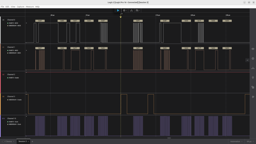
The second capture is the display’s chip ID read, which begin() does while it starts the RA8875. Now the RA8875 chip-select (D2) is low and the FRAM’s (D3) is high. The library selects register 0 (0x80, 0x00), then reads it (0x40 followed by a dummy byte), and the chip answers 0x75, the ID that begin() checks for. The transfers that follow begin the controller’s PLL setup (register 0x88).
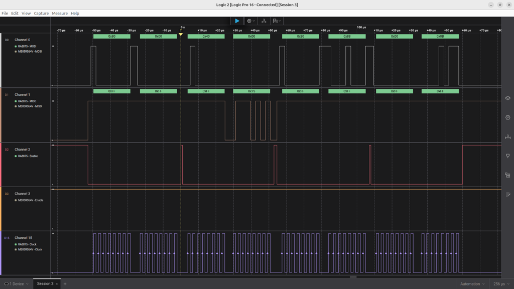
Only one chip-select is ever low at a time, and the clock, MOSI and MISO lines carry the traffic of whichever device is selected. That is how the display and the FRAM share one SPI bus.
Project Downloads
The complete STM32 FRAM touch calibration project used in this tutorial is available for download in several parts. The source download contains this project’s own files; the three library downloads, STM32_GFX, STM32_RA8875 and STM32_MB85RS64V, go into the project root (see Getting the Libraries above).
- Project source: Core/ sources, IOC file and IOC report, linker scripts, README.md and LICENSE
- Libraries: STM32_GFX, STM32_RA8875 and STM32_MB85RS64V, one zip each
- Doxygen documentation (docs/html/index.html)
Documentation
The documentation is generated from the project source and all three libraries in a single Doxygen run, so index.html covers everything, and every function in the libraries and in this project has its own description. It is included as the separate download above; extract it and open:
F439_CPP_SPI_RA8875_TFT_LCD_04/docs/html/index.htmlin a web browser. The documentation describes each function and data structure, including the thread-safety notes, and how the modules interact.
If you have questions or run into trouble getting the boards programmed and talking to each other, post in the Tutorial Support forum and I will work through it with you. If project source is not linked in the tutorial, it may be available on request — use the email contact option in the site footer.