Overview
This tutorial covers STM32 HC-SR04 ultrasonic sensor interface and distance measurement using an STM32 Nucleo-F103RB microcontroller. The HC-SR04 measures distance by emitting a short ultrasonic burst on the TRIG pin and measuring the duration of the ECHO pulse that returns. TIM1 is configured as an input capture timer running at 1 MHz — giving 1 µs resolution — to measure the ECHO pulse width precisely. The measured pulse width is then converted to distance in centimeters and inches and printed to a serial console via USART3.
What You Will Learn
- How to wire the HC-SR04 TRIG and ECHO pins to the Nucleo-F103RB
- How to configure TIM1 as an input capture timer at 1 MHz resolution in STM32CubeIDE
- How to implement the TRIG pulse and ECHO measurement using HAL_TIM_IC_CaptureCallback
- How to convert the measured pulse width to distance in centimeters and inches
- How to output distance readings to a serial console via USART3
Prerequisites
This tutorial assumes basic familiarity with STM32CubeIDE, GPIO configuration, timer peripherals, and UART communication on STM32 microcontrollers.
Materials List
Project Structure
F103RB_C_HCSR04_Ultrasonic_Sensor
├── Core
│   ├── Inc
│   │   └── main.h
│   └── Src
│       └── main.c
├── F103RB_C_HCSR04_Ultrasonic_Sensor.pdf
└── STM32F103RBTX_FLASH.ld
Hardware Configuration / Pinouts
Overview
The HC-SR04 sensor has four pins: VCC (5V), GND, TRIG, and ECHO. The TRIG pin is connected to PA9 on the Nucleo-F103RB and configured as a GPIO output. A 10 µs HIGH pulse on TRIG triggers the sensor to emit an ultrasonic burst. The ECHO pin is connected to PA8 and configured as TIM1 Channel 1 input capture — the timer measures the duration of the HIGH pulse returned on ECHO, which is proportional to the distance of the target. For complete Nucleo-F103RB pin assignments including Arduino and Morpho headers, see the Nucleo-F103RB Pinout reference page.
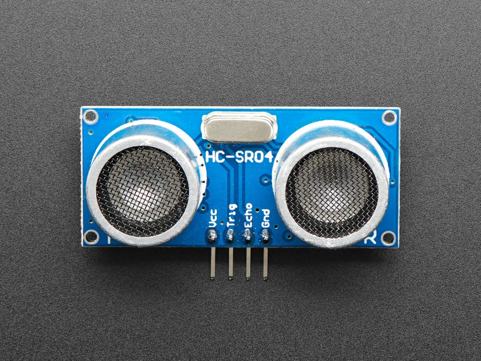
For full HC-SR04 electrical specifications and timing diagrams, refer to the HC-SR04 Datasheet.
Schematic

[INSERT FTDI IMAGE AND PINOUT HERE]
Pinouts & Configurations
[INSERT FILE BLOCK HERE — IOC PDF]
Project Setup
Create a new STM32CubeIDE project targeting the STM32F103RBTx. In STM32CubeMX, configure the following peripherals:
- PA9 — GPIO Output (TRIG pin)
- TIM1 Channel 1 (PA8) — Input Capture Direct Mode, rising edge, prescaler 72-1 for 1 MHz resolution, period 65535
- USART3 — Asynchronous, 19200 baud, 8N1
Enable the TIM1 Capture Compare interrupt in the NVIC settings. Generate the project code and open it in STM32CubeIDE.
Code Walkthrough
All application code resides in Core/Src/main.c and Core/Inc/main.h. The sections below walk through each key part.
main.h — Pin Definitions
The TRIG and ECHO pin assignments are defined as macros in main.h for easy reference throughout the code.
#define TRIG_PIN GPIO_PIN_9
#define TRIG_PORT GPIOA

#define ECHO_PIN GPIO_PIN_8
#define ECHO_PORT GPIOAdelayus() — Microsecond Delay
TIM1 is also used to generate a precise microsecond delay required for the TRIG pulse. The counter is reset to zero and the function busy-waits until the counter reaches the requested number of microseconds. This works because TIM1 is configured with a 1 MHz tick rate.
void delayus(uint16_t time)
{
	__HAL_TIM_SET_COUNTER(&htim1, 0);
	while (__HAL_TIM_GET_COUNTER(&htim1) < time);
}hcsr04Read() — Trigger Pulse
The hcsr04Read() function drives the TRIG pin HIGH for 10 µs then pulls it LOW, which commands the HC-SR04 to emit an ultrasonic burst. It then enables the TIM1 Channel 1 capture interrupt so the ECHO pulse can be measured.
void hcsr04Read(void)
{
	HAL_GPIO_WritePin(TRIG_PORT, TRIG_PIN, GPIO_PIN_SET);  // pull the TRIG pin HIGH
	delayus(10);  // wait for 10 us
	HAL_GPIO_WritePin(TRIG_PORT, TRIG_PIN, GPIO_PIN_RESET);  // pull the TRIG pin LOW

	__HAL_TIM_ENABLE_IT(&htim1, TIM_IT_CC1);
}HAL_TIM_IC_CaptureCallback() — ECHO Measurement
This callback fires on every TIM1 Channel 1 capture event. On the first capture (rising edge of ECHO) the timer value is saved and the polarity is switched to falling edge. On the second capture (falling edge) the difference between the two values gives the ECHO pulse width in microseconds. The distance is then calculated using the formula: distance = difference * 0.034 / 2, where 0.034 cm/µs is the speed of sound and dividing by 2 accounts for the round trip. A timer counter rollover case is also handled.
void HAL_TIM_IC_CaptureCallback(TIM_HandleTypeDef *htim)
{
	if (htim->Channel == HAL_TIM_ACTIVE_CHANNEL_1) {
		if (!isFirstCaptured) {

			hcsr04Val1 = HAL_TIM_ReadCapturedValue(htim, TIM_CHANNEL_1);
			isFirstCaptured = true;

			// Switch to falling edge
			__HAL_TIM_SET_CAPTUREPOLARITY(htim, TIM_CHANNEL_1, TIM_INPUTCHANNELPOLARITY_FALLING);
		} else {
			hcsr04Val2 = HAL_TIM_ReadCapturedValue(htim, TIM_CHANNEL_1);
			__HAL_TIM_SET_COUNTER(htim, 0);

			if (hcsr04Val2 >= hcsr04Val1) {
				difference = hcsr04Val2 - hcsr04Val1;
			} else {
				if (hcsr04Val1 > hcsr04Val2) {
					difference = (0xffff - hcsr04Val1) + hcsr04Val2;
				}
			}

			distance = difference * .034 / 2;
			isFirstCaptured = false;

			// Switch back to rising edge
			__HAL_TIM_SET_CAPTUREPOLARITY(htim, TIM_CHANNEL_1, TIM_INPUTCHANNELPOLARITY_RISING);
			__HAL_TIM_DISABLE_IT(&htim1, TIM_IT_CC1);
		}
	}
}main() — Main Loop
The main loop calls hcsr04Read() once per second and prints the distance in both centimeters and inches to the serial console via USART3.
HAL_TIM_IC_Start_IT(&htim1, TIM_CHANNEL_1);

while (1)
{
	hcsr04Read();

	printf("%.02f cm = %.02f inches\r\n", distance * 1.0, distance * 0.393701);

	HAL_Delay(1000);
}USART Ouput

[INSERT USART OUTPUT SCREENSHOT HERE]
Project Downloads
The complete project source code used in this tutorial is available for download. This includes all necessary files to build and run the project, along with supporting documentation.
If you have questions or run into trouble getting the boards programmed and talking to each other, post in the Tutorial Support forum and I will work through it with you. If project source is not linked in the tutorial, it may be available on request — use the email contact option in the site footer.