Overview
This tutorial reads the STM32 device electronic signature — the 96-bit factory-programmed unique device ID, the DBGMCU device/revision ID, and the flash capacity register — and prints all of it over the standard debug USART. Every register this project reads is internal to the MCU: there is no external circuitry involved at all, so the logic here is identical on any STM32 board, regardless of family or package. The Nucleo-H753ZI used for the build in this post is purely a convenience — it reuses the same USART1/FTDI debug setup as this site’s other H753 tutorials — not a requirement.
This is a from-scratch revision of the site’s older STM32 Unique ID Retrieve 96-Bit Device Electronic Signature tutorial. That original project ran the UID through a third-party 32-bit hash function before printing anything — and had a real bug in that step, hashing the wrong variable — while never actually printing anything over serial at all, despite the whole point being to read and report the UID. This revision drops the hash entirely, adds real USART output, and reads two additional registers (device/revision ID and flash capacity) the original never touched.
What You Will Learn
- How to read an STM32’s 96-bit factory-programmed unique device ID with
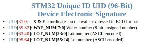
HAL_GetUIDw0/1/2(), and what its internal structure (wafer coordinates, lot number) actually means - How to read the rest of ST’s “device electronic signature” —
DBGMCU->IDCODE(device ID and silicon revision ID) and the flash capacity register atFLASHSIZE_BASE— and why device ID, revision ID, and unique ID each mean something different - Why every register this project reads is completely independent of which board it’s mounted on — and why that means this entire tutorial’s logic works unchanged on any STM32, not just a Nucleo-H753ZI
- How to use the UID to make one shared firmware image self-select its role (e.g. transmitter vs. receiver) at boot, with a real example from this site’s LoRa project — and the compile-time
#ifdefalternative, with the tradeoffs between the two approaches
Prerequisites
You should be comfortable creating and building a basic STM32CubeIDE project. No prior SPI/I2C/peripheral-wiring experience is needed — this project touches no external hardware at all. Debug output is redirected to printf over USART1 through an external FTDI USB-to-serial adapter — the same standard debug setup used throughout this site’s tutorials; the Hardware Configuration section below covers the wiring.
Materials List
- Nucleo-H753ZI development board — or literally any STM32 Nucleo board; see “Board independence” below
- FTDI USB-to-serial adapter, for USART1 debug output
- USB cable (Micro-USB or USB-C, depending on your Nucleo board’s ST-LINK connector)
Board Diagram
Project Structure
H753_CPP_Device_Electronic_Signature/
├── Core/
│   ├── Inc/
│   │   └── main.h
│   └── Src/
│       └── main.c
├── Doxyfile
├── H753_CPP_Device_Electronic_Signature.ioc
├── H753_CPP_Device_Electronic_Signature.pdf
├── H753_CPP_Device_Electronic_Signature.txt
├── LICENSE
├── README.md
├── project_mainpage.dox
├── STM32H753ZITX_FLASH.ld
└── STM32H753ZITX_RAM.ld
Hardware Configuration / Pinouts
Overview
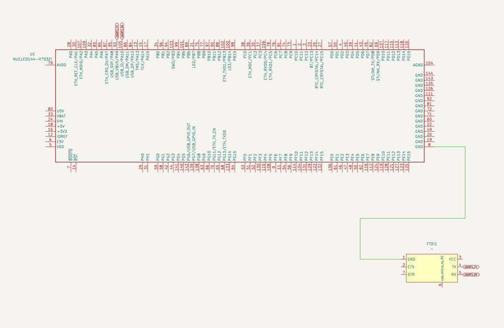
There is no external circuitry in this project at all. Every value that makes up the device electronic signature — the unique ID, the device/revision ID, and the flash capacity — comes from a register that’s internal to the MCU itself, at a fixed memory address, with no peripheral initialization beyond the debug USART needed to print the results. The schematic below is effectively just the Nucleo board and the FTDI debug adapter.
| Signal | Nucleo-H753ZI Pin | Function |
|---|---|---|
| USART1 TX | PA9 | Debug console, to FTDI RX |
| USART1 RX | PA10 | Debug console, from FTDI TX |
Debug output uses the standard USART1 setup on this site: PA9 (TX) and PA10 (RX), asynchronous mode, through an external FTDI USB-to-serial adapter rather than the board’s onboard ST-LINK virtual COM port.
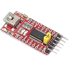
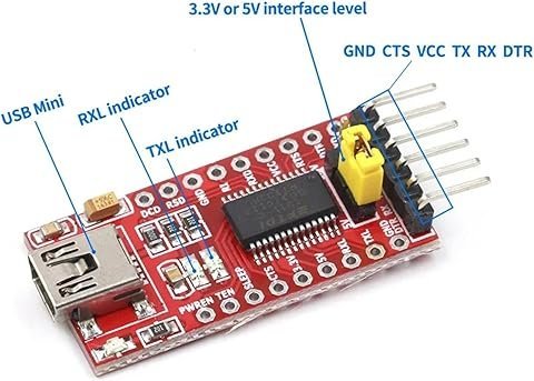
FTDI Pinouts
FTDI to USB Pinout from right to left
- Pin 1 – GND
- Pin 4 – TX
- Pin 5 – RX
- USB Mini – Connect to PC via USB cable
Make sure the jumper is set to 5V — the FTDI board is powered from the USB mini cable, and a computer’s USB port supplies 5V.
Schematic
Pinouts & Configurations
The complete CubeMX pin assignment and peripheral configuration is captured in the IOC report below.
Project Setup
Create a new STM32CubeIDE project targeting the Nucleo-H753ZI board (or any STM32 board — see “Board independence” above), with C++ enabled. In the .ioc pinout view:
- Enable USART1 in Asynchronous mode on PA9/PA10 for
printfredirect, per this site’s standard debug UART convention. Nothing else needs to be enabled — no other peripheral is touched by this project.
Code Walkthrough
Unlike this site’s driver-class-based tutorials (the W25Q flash projects, for example), reading the device electronic signature doesn’t need a dedicated driver class or a C/C++ bridge — three fixed registers and printing them is small enough that a class would be pure overhead, not a simplification. Everything lives directly in main.c.
main.c — reading and printing the device electronic signature
After clock and peripheral init, this reads the 96-bit unique ID via HAL_GetUIDw0/1/2() — three consecutive internal register reads, with no hashing or repacking, since the raw 96 bits already are the identifier. It then reads DBGMCU->IDCODE (split into a device ID that’s identical for every STM32H753ZI ever made, and a revision ID that identifies the silicon stepping and can differ by manufacturing batch) and the flash capacity register at FLASHSIZE_BASE, and prints all of it as a labeled report. The comments in the code below walk through exactly why each read is done the way it is, what the UID’s internal structure actually encodes per ST’s reference manual, and a worked comparison of using the UID at runtime vs. a compile-time #ifdef to make one firmware image behave differently depending on which physical board it’s running on.
/* USER CODE BEGIN Header */
/**
  ******************************************************************************
  * @file           : main.c
  * @brief          : Main program body
  ******************************************************************************
  * @attention
  *
  * Copyright (c) 2026 STMicroelectronics.
  * All rights reserved.
  *
  * This software is licensed under terms that can be found in the LICENSE file
  * in the root directory of this software component.
  * If no LICENSE file comes with this software, it is provided AS-IS.
  *
  ******************************************************************************
  */
/* USER CODE END Header */
/* Includes ------------------------------------------------------------------*/
#include "main.h"

/* Private includes ----------------------------------------------------------*/
/* USER CODE BEGIN Includes */
#include <stdio.h>

/* USER CODE END Includes */

/* Private typedef -----------------------------------------------------------*/
/* USER CODE BEGIN PTD */

/* USER CODE END PTD */

/* Private define ------------------------------------------------------------*/
/* USER CODE BEGIN PD */

/* USER CODE END PD */

/* Private macro -------------------------------------------------------------*/
/* USER CODE BEGIN PM */

/* USER CODE END PM */

/* Private variables ---------------------------------------------------------*/

UART_HandleTypeDef huart1;

/* USER CODE BEGIN PV */

/* USER CODE END PV */

/* Private function prototypes -----------------------------------------------*/
void SystemClock_Config(void);
static void MX_GPIO_Init(void);
static void MX_USART1_UART_Init(void);
/* USER CODE BEGIN PFP */

/* USER CODE END PFP */

/* Private user code ---------------------------------------------------------*/
/* USER CODE BEGIN 0 */

#ifdef REDIRECT_PRINTF
#define PUTCHAR_PROTOTYPE int __io_putchar(int ch)

PUTCHAR_PROTOTYPE
{
  HAL_UART_Transmit(&huart1, (uint8_t *)&ch, 1, 0xFFFF);

  return ch;
}
#endif

/* USER CODE END 0 */

/**
  * @brief  The application entry point.
  * @retval int
  */
int main(void)
{

  /* USER CODE BEGIN 1 */

  /* USER CODE END 1 */

  /* MCU Configuration--------------------------------------------------------*/

  /* Reset of all peripherals, Initializes the Flash interface and the Systick. */
  HAL_Init();

  /* USER CODE BEGIN Init */

  /* USER CODE END Init */

  /* Configure the system clock */
  SystemClock_Config();

  /* USER CODE BEGIN SysInit */

  /* USER CODE END SysInit */

  /* Initialize all configured peripherals */
  MX_GPIO_Init();
  MX_USART1_UART_Init();
  /* USER CODE BEGIN 2 */

  printf("\x1b[2J\x1b[H");	// Clear the dumb terminal screen

  /*
   * Every STM32 has a factory-programmed 96-bit unique device identifier
   * fused into silicon at manufacture time -- three consecutive 32-bit
   * words. HAL_GetUIDw0/1/2() reads it via the HAL's dedicated accessors
   * rather than dereferencing the UID base address directly, which keeps
   * this code portable: the actual register address differs per STM32
   * family, and HAL hides that difference behind the same three function
   * calls on every one of them.
   *
   * No hashing, no packing into a shorter derived value -- the raw 96
   * bits already ARE the identifier. An earlier version of this
   * tutorial ran the UID through a third-party 32-bit hash function
   * before printing anything; that added a dependency and a place for
   * bugs to hide (the earlier version had one -- it hashed the wrong
   * variable and never printed the hash result at all) without buying
   * anything real for what this demo actually needs: identifying one
   * specific, already-known board.
   */
  uint32_t uid[3];
  uid[0] = HAL_GetUIDw0();
  uid[1] = HAL_GetUIDw1();
  uid[2] = HAL_GetUIDw2();

  /*
   * The 96 bits aren't arbitrary either -- ST's reference manual (RM0433,
   * "Device electronic signature" > "Unique device ID register") documents
   * an internal structure baked into these three words at manufacture
   * time: the first word encodes the die's X/Y coordinates on the silicon
   * wafer plus a wafer number, and the remaining two words together
   * encode a 7-character lot number as ASCII text. This is genuinely how
   * ST tracks a chip back to its manufacturing batch, not something added
   * by this tutorial.
   *
   * This tutorial deliberately does NOT parse those sub-fields out here:
   * the exact bit boundaries are given in a table in RM0433 and are worth
   * reading directly from ST's own documentation rather than copying a
   * bit-shift from a tutorial that could get a boundary wrong -- printing
   * the three raw words, as done below, is already sufficient to uniquely
   * identify this specific chip for the UID-comparison use case this
   * tutorial is actually built around.
   */

  /*
   * The UID isn't the only factory-programmed identification data on an
   * STM32 -- ST groups it together with two more registers under the
   * name "electronic signature" in the reference manual, and both are
   * read the same simple way: a fixed memory address, no peripheral
   * init required.
   *
   * DBGMCU->IDCODE identifies the SILICON ITSELF, not this individual
   * chip or which board it happens to be soldered onto -- the same
   * STM32H753ZI chip reports the identical value here whether it's on a
   * Nucleo-H753ZI, a custom PCB, or any other carrier board. The two
   * halves of this register don't carry the same guarantee, though:
   *   - DEV_ID identifies the part/die family and is identical for
   *     EVERY STM32H753ZI ever manufactured, full stop.
   *   - REV_ID identifies the silicon REVISION (stepping) -- it can
   *     differ between manufacturing batches of the same part number if
   *     ST ever revises the silicon (e.g. to fix an erratum), so two
   *     STM32H753ZI chips can legitimately report the same DEV_ID but a
   *     different REV_ID.
   * This is different from the UID above either way: UID is unique PER
   * CHIP, DEV_ID/REV_ID describe the part and its silicon revision, not
   * the individual chip.
   */
  uint32_t devId = DBGMCU->IDCODE & DBGMCU_IDCODE_DEV_ID_Msk;
  uint32_t revId = (DBGMCU->IDCODE & DBGMCU_IDCODE_REV_ID_Msk) >> DBGMCU_IDCODE_REV_ID_Pos;

  /*
   * FLASHSIZE_BASE holds this specific part's flash capacity in
   * Kbytes, as a 16-bit half-word. Useful on STM32 product lines sold
   * in multiple flash-size variants under the same part family, so
   * firmware (or a bootloader) can confirm at runtime how much flash it
   * actually has to work with instead of assuming from the part number
   * on the box.
   */
  uint16_t flashSizeKb = *(__IO uint16_t *)FLASHSIZE_BASE;

  printf("\r\n=== STM32H753ZI Device Electronic Signature ===\r\n\r\n");

  printf("Unique Device ID (96-bit, factory-programmed, unique per chip):\r\n");
  printf("  Word 0 : 0x%08lX\r\n", (unsigned long)uid[0]);
  printf("  Word 1 : 0x%08lX\r\n", (unsigned long)uid[1]);
  printf("  Word 2 : 0x%08lX\r\n\r\n", (unsigned long)uid[2]);

  printf("Device Identification (DBGMCU->IDCODE -- board-independent):\r\n");
  printf("  Device ID   : 0x%03lX (same for every H753ZI)\r\n", (unsigned long)devId);
  printf("  Revision ID : 0x%04lX (silicon revision -- can vary by mfg batch)\r\n\r\n", (unsigned long)revId);

  printf("Flash Capacity (FLASHSIZE_BASE):\r\n");
  printf("  %u Kbytes\r\n\r\n", flashSizeKb);

  /*
   * Practical use: hardcode a known board's three UID words and compare
   * against them at boot to make one compiled firmware image behave
   * differently depending on which physical board it's actually running
   * on -- no jumpers, DIP switches, or external ID hardware needed.
   *
   * This is exactly how F439_CPP_TX-RX_LoRa_Project_01 (a two-board LoRa
   * link) picks its role at startup: both boards run the IDENTICAL
   * compiled binary, and a plain three-word comparison against each
   * board's own known UID decides transmitter vs. receiver, e.g.:
   *
   *   if (uid[0]==RX_UID0 && uid[1]==RX_UID1 && uid[2]==RX_UID2) {
   *       role = ROLE_RX;
   *   } else if (uid[0]==TX_UID0 && uid[1]==TX_UID1 && uid[2]==TX_UID2) {
   *       role = ROLE_TX;
   *   }
   *
   * The alternative -- two separate firmware builds, one compiled for
   * "the TX board" and one for "the RX board" -- means every shared bug
   * fix has to be made and tested twice, and the two builds can quietly
   * drift apart over time. One binary that self-selects its role from a
   * hardware-guaranteed identity sidesteps both problems.
   *
   * The compile-time alternative to all of this is a preprocessor
   * #ifdef, with the role macro set per build configuration instead of
   * detected from the UID at runtime:
   *
   *   #ifdef ROLE_TX
   *       // transmitter-only code
   *   #elif defined(ROLE_RX)
   *       // receiver-only code
   *   #endif
   *
   * That sidesteps ever needing to know a board's UID in advance -- but
   * it brings back the exact two-binary problem the UID check was meant
   * to avoid: one build per role, each needing its own flash step, and
   * shared logic edited in one path has to be mirrored (or refactored
   * out) in the other. Runtime UID comparison trades "must know the
   * UIDs ahead of time" for "only one binary to build, test, and flash";
   * #ifdef trades that back the other way. Which one is right depends on
   * whether the boards' identities are fixed and known ahead of time
   * (favors UID comparison) or the role needs to be decided at build
   * time before any hardware exists to read a UID from (favors #ifdef).
   */

  /* USER CODE END 2 */

  /* Infinite loop */
  /* USER CODE BEGIN WHILE */
  while (1)
  {
    /* USER CODE END WHILE */

    /* USER CODE BEGIN 3 */
  }
  /* USER CODE END 3 */
}

/**
  * @brief System Clock Configuration
  * @retval None
  */
void SystemClock_Config(void)
{
  RCC_OscInitTypeDef RCC_OscInitStruct = {0};
  RCC_ClkInitTypeDef RCC_ClkInitStruct = {0};

  /** Supply configuration update enable
  */
  HAL_PWREx_ConfigSupply(PWR_LDO_SUPPLY);

  /** Configure the main internal regulator output voltage
  */
  __HAL_PWR_VOLTAGESCALING_CONFIG(PWR_REGULATOR_VOLTAGE_SCALE0);

  while(!__HAL_PWR_GET_FLAG(PWR_FLAG_VOSRDY)) {}

  /** Initializes the RCC Oscillators according to the specified parameters
  * in the RCC_OscInitTypeDef structure.
  */
  RCC_OscInitStruct.OscillatorType = RCC_OSCILLATORTYPE_HSI;
  RCC_OscInitStruct.HSIState = RCC_HSI_DIV1;
  RCC_OscInitStruct.HSICalibrationValue = RCC_HSICALIBRATION_DEFAULT;
  RCC_OscInitStruct.PLL.PLLState = RCC_PLL_ON;
  RCC_OscInitStruct.PLL.PLLSource = RCC_PLLSOURCE_HSI;
  RCC_OscInitStruct.PLL.PLLM = 4;
  RCC_OscInitStruct.PLL.PLLN = 60;
  RCC_OscInitStruct.PLL.PLLP = 2;
  RCC_OscInitStruct.PLL.PLLQ = 5;
  RCC_OscInitStruct.PLL.PLLR = 2;
  RCC_OscInitStruct.PLL.PLLRGE = RCC_PLL1VCIRANGE_3;
  RCC_OscInitStruct.PLL.PLLVCOSEL = RCC_PLL1VCOWIDE;
  RCC_OscInitStruct.PLL.PLLFRACN = 0;
  if (HAL_RCC_OscConfig(&RCC_OscInitStruct) != HAL_OK)
  {
    Error_Handler();
  }

  /** Initializes the CPU, AHB and APB buses clocks
  */
  RCC_ClkInitStruct.ClockType = RCC_CLOCKTYPE_HCLK|RCC_CLOCKTYPE_SYSCLK
                              |RCC_CLOCKTYPE_PCLK1|RCC_CLOCKTYPE_PCLK2
                              |RCC_CLOCKTYPE_D3PCLK1|RCC_CLOCKTYPE_D1PCLK1;
  RCC_ClkInitStruct.SYSCLKSource = RCC_SYSCLKSOURCE_PLLCLK;
  RCC_ClkInitStruct.SYSCLKDivider = RCC_SYSCLK_DIV1;
  RCC_ClkInitStruct.AHBCLKDivider = RCC_HCLK_DIV2;
  RCC_ClkInitStruct.APB3CLKDivider = RCC_APB3_DIV2;
  RCC_ClkInitStruct.APB1CLKDivider = RCC_APB1_DIV2;
  RCC_ClkInitStruct.APB2CLKDivider = RCC_APB2_DIV2;
  RCC_ClkInitStruct.APB4CLKDivider = RCC_APB4_DIV2;

  if (HAL_RCC_ClockConfig(&RCC_ClkInitStruct, FLASH_LATENCY_4) != HAL_OK)
  {
    Error_Handler();
  }
}

/**
  * @brief USART1 Initialization Function
  * @param None
  * @retval None
  */
static void MX_USART1_UART_Init(void)
{

  /* USER CODE BEGIN USART1_Init 0 */

  /* USER CODE END USART1_Init 0 */

  /* USER CODE BEGIN USART1_Init 1 */

  /* USER CODE END USART1_Init 1 */
  huart1.Instance = USART1;
  huart1.Init.BaudRate = 19200;
  huart1.Init.WordLength = UART_WORDLENGTH_8B;
  huart1.Init.StopBits = UART_STOPBITS_1;
  huart1.Init.Parity = UART_PARITY_NONE;
  huart1.Init.Mode = UART_MODE_TX_RX;
  huart1.Init.HwFlowCtl = UART_HWCONTROL_NONE;
  huart1.Init.OverSampling = UART_OVERSAMPLING_16;
  huart1.Init.OneBitSampling = UART_ONE_BIT_SAMPLE_DISABLE;
  huart1.Init.ClockPrescaler = UART_PRESCALER_DIV1;
  huart1.AdvancedInit.AdvFeatureInit = UART_ADVFEATURE_NO_INIT;
  if (HAL_UART_Init(&huart1) != HAL_OK)
  {
    Error_Handler();
  }
  if (HAL_UARTEx_SetTxFifoThreshold(&huart1, UART_TXFIFO_THRESHOLD_1_8) != HAL_OK)
  {
    Error_Handler();
  }
  if (HAL_UARTEx_SetRxFifoThreshold(&huart1, UART_RXFIFO_THRESHOLD_1_8) != HAL_OK)
  {
    Error_Handler();
  }
  if (HAL_UARTEx_DisableFifoMode(&huart1) != HAL_OK)
  {
    Error_Handler();
  }
  /* USER CODE BEGIN USART1_Init 2 */

  /* USER CODE END USART1_Init 2 */

}

/**
  * @brief GPIO Initialization Function
  * @param None
  * @retval None
  */
static void MX_GPIO_Init(void)
{
  /* USER CODE BEGIN MX_GPIO_Init_1 */

  /* USER CODE END MX_GPIO_Init_1 */

  /* GPIO Ports Clock Enable */
  __HAL_RCC_GPIOC_CLK_ENABLE();
  __HAL_RCC_GPIOH_CLK_ENABLE();
  __HAL_RCC_GPIOA_CLK_ENABLE();

  /* USER CODE BEGIN MX_GPIO_Init_2 */

  /* USER CODE END MX_GPIO_Init_2 */
}

/* USER CODE BEGIN 4 */


/**
 * @brief  This function is executed in case of error occurrence.
 * @param  file The file name as a string.
 * @param  line The line number in the file.
 * @retval None
 */
void _Error_Handler(const char *file, int line)
{
	__disable_irq();

#ifdef REDIRECT_PRINTF
	char buf[80];

	snprintf(buf, sizeof(buf),
			"Trapped in _Error_Handler(). Called from: %s, line: %d\r\n",
			file, line);
	printf("%s", buf);
#endif

	/* User can add an implementation to report the HAL error return state. */
	while(1)
	{
	}
}

/* USER CODE END 4 */


#ifdef  USE_FULL_ASSERT
/**
  * @brief  Reports the name of the source file and the source line number
  *         where the assert_param error has occurred.
  * @param  file: pointer to the source file name
  * @param  line: assert_param error line source number
  * @retval None
  */
void assert_failed(uint8_t *file, uint32_t line)
{
  /* USER CODE BEGIN 6 */
  /* assert_param() can fire from inside any HAL call -- including before
   * REDIRECT_PRINTF's UART is fully set up, or from an unusual calling
   * context -- so this only attempts to report when REDIRECT_PRINTF is
   * available, then halts either way. Continuing after a failed HAL
   * parameter check is undefined behavior, not something safe to log
   * and ignore. */
  __disable_irq();

#ifdef REDIRECT_PRINTF
  {
    char buf[96];

    snprintf(buf, sizeof(buf),
             "assert_param failed: file %s, line %lu\r\n",
             (char *)file, (unsigned long)line);
    printf("%s", buf);
  }
#endif

  while (1)
  {
  }
  /* USER CODE END 6 */
}
#endif /* USE_FULL_ASSERT */The old tutorial’s featured image is worth reusing here — it’s a genuinely accurate bit-level breakdown of the UID’s internal structure, and nothing about it changed with this revision (only what the firmware does with the UID changed). ST’s own community knowledge base confirms the same structure independently: How to obtain and use the STM32 96-bit UID.
Practical use: picking a board’s role from its UID
Reading a UID is only half the story — the useful part is what you do with it. A real example from this site: the STM32 SX1262 Encrypted LoRa project is a two-board LoRa link where the transmitter and receiver run the identical compiled firmware image. Instead of maintaining two separate builds, the code reads its own UID at boot and compares it against two hardcoded, already-known UID sets — one per physical board — to decide which role to play:
if (uid[0]==RX_UID0 && uid[1]==RX_UID1 && uid[2]==RX_UID2) {
    role = ROLE_RX;
} else if (uid[0]==TX_UID0 && uid[1]==TX_UID1 && uid[2]==TX_UID2) {
    role = ROLE_TX;
}No jumpers, no DIP switches, no separate “TX build” and “RX build” to keep in sync — just onefor firmware image that already knows, from hardware-guaranteed identity, which board it’s running on. The tradeoff is that both UIDs have to be known ahead of time (read them once with this project’s own firmware, then hardcode them into the LoRa project). The alternative is a compile-time #ifdef ROLE_TX / #ifdef ROLE_RX switch instead — that sidesteps ever needing to know a UID in advance, but brings back the two-separate-builds problem this technique avoids. See the comments in main.c below for the fuller comparison.
Real hardware output
Captured from a real run on a Nucleo-H753ZI over the FTDI debug UART:
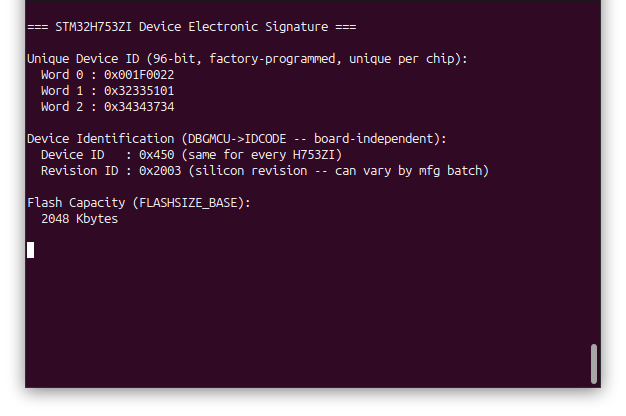
Device ID 0x450 matches ST’s documented ID for the STM32H742/743/750/753 family, and 2048 Kbytes matches the H753ZI’s actual 2 MByte flash spec — a good cross-check that these register reads are correct, not just plausible-looking numbers. Word 2 of the UID (0x34343734) even decodes byte-by-byte as ASCII (4, 4, 7, 4), a small real-world confirmation of the lot-number-as-ASCII structure shown in the diagram above — even though this project deliberately doesn’t parse that sub-field out in code.
Documentation
This project includes Doxygen-generated documentation built from the inline comments in main.c, covering the register reads and the UID-comparison/#ifdef role-selection discussion.
The documentation is available as a separate download in the Project Downloads section below. Once downloaded, view it locally by opening:
docs/html/index.htmlin a web browser.
Project Downloads
The complete project source code used in this tutorial is available for download, along with the browsable Doxygen documentation. The IOC configuration is available above in the Pinouts & Configurations section — regenerate the CubeMX project from it, then drop in the source below.
- Application Source (main.c / main.h)
- Linker Scripts (STM32H753ZITX_FLASH.ld / STM32H753ZITX_RAM.ld)
Browsable Doxygen documentation for main.c‘s register reads and the role-selection discussion:
If you have questions or run into trouble getting the boards programmed and talking to each other, post in the Tutorial Support forum and I will work through it with you. If project source is not linked in the tutorial, it may be available on request — use the email contact option in the site footer.