Overview
This tutorial covers STM32 28BYJ-48 stepper motor control using a ULN2003 driver board and an STM32F103C8. Four GPIO pins on the STM32 feed the ULN2003 inputs, which switch the motor’s coils through a Darlington array. By driving those four lines through an 8-step half-step sequence, the firmware rotates the motor shaft in either direction, with a TIM2 microsecond timebase setting the delay between steps — and therefore the speed. USART1 prints each coil pattern at 19200 baud so you can watch the sequence on a serial terminal as the motor turns.
What You Will Learn
- How a 28BYJ-48 unipolar stepper motor and a ULN2003 driver board work together
- Wiring the ULN2003 IN1–IN4 inputs to STM32F103 GPIO pins (PA6, PA5, PA4, PA3)
- Generating the 8-step half-step drive sequence in firmware for clockwise and counter-clockwise rotation
- Using TIM2 as a microsecond timebase to set step timing, and thus motor speed
- Retargeting
printfover USART1 to trace the coil energizing pattern in real time
Prerequisites
This tutorial assumes you can create and build a project in STM32CubeIDE, configure GPIO pins as push-pull outputs, and flash an STM32F103C8 board. You should also be comfortable opening a serial terminal at 19200 baud to view the debug output. No prior stepper-motor experience is required — the drive sequence is explained step by step in the Code Walkthrough.
Materials List
- STM32F103C8 development board
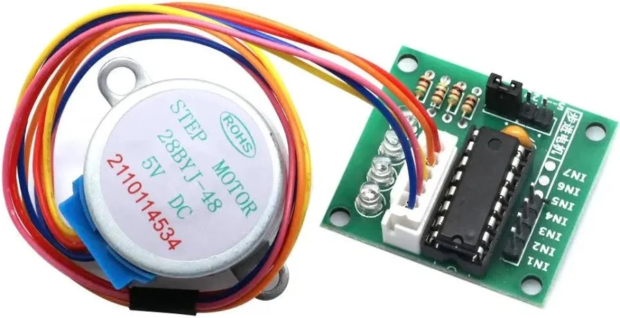
- 28BYJ-48 5 V unipolar stepper motor
- ULN2003 driver board (the board commonly bundled with the 28BYJ-48)
- USB-to-UART adapter (e.g. CP2102 or FTDI) for the serial debug output
- ST-Link V2 programmer for flashing
Board Diagram
Stepper Motor Detailed Functional Overview
Detailed Description of how a 28BYJ-48 Stepper Motor is built
Stepper Motor Pinout Diagram
Download ULN2xxx Seven Darlington arrays Datasheet PDF file

ULN2003 Driver Board Diagram

ULN2003 Module Pinout Diagram

The previous images were courtesy of: Controlling a 28BYJ-48 Stepper Motor Using ULN2003 and Arduino
Project Structure
./F103_C_28BYJ-48_StepMotor_ULN2003
├── Core
│   ├── Inc
│   │   ├── main.h
│   │   ├── stm32f1xx_hal_conf.h
│   │   └── stm32f1xx_it.h
│   ├── Src
│   │   ├── main.c
│   │   ├── stm32f1xx_hal_msp.c
│   │   ├── stm32f1xx_it.c
│   │   ├── syscalls.c
│   │   ├── sysmem.c
│   │   └── system_stm32f1xx.c
│   └── Startup
│       └── startup_stm32f103c8tx.s
├── Drivers
│   ├── CMSIS
│   └── STM32F1xx_HAL_Driver
├── F103_C_28BYJ-48_StepMotor_ULN2003.ioc
├── F103_C_28BYJ-48_StepMotor_ULN2003.pdf
└── STM32F103C8TX_FLASH.ld
Hardware Configuration / Pinouts
Overview
The 28BYJ-48 is a 5 V unipolar stepper with four coils. Those coils can’t be driven directly from the STM32’s GPIO pins — they need more current than a microcontroller pin can supply — so the ULN2003 driver board sits in between. The board’s ULN2003 chip is a set of Darlington transistors: each of its four inputs (IN1–IN4) switches one motor coil to ground, and its onboard LEDs mirror the coil states, which is handy while debugging.
The wiring is straightforward. Four STM32 GPIO outputs drive IN1–IN4 on the driver board, the motor plugs into the board’s 5-pin connector, and the board is powered from a 5 V supply. Make sure the STM32 and the driver board share a common ground, otherwise the input signals have no reference. A separate USB-to-UART adapter connects to USART1 so you can watch the step pattern on a serial terminal.
| Signal | STM32F103C8 pin | Configuration | Connects to |
|---|---|---|---|
| ULN2003 IN1 | PA6 | GPIO output, push-pull | IN1 on driver board |
| ULN2003 IN2 | PA5 | GPIO output, push-pull | IN2 on driver board |
| ULN2003 IN3 | PA4 | GPIO output, push-pull | IN3 on driver board |
| ULN2003 IN4 | PA3 | GPIO output, push-pull | IN4 on driver board |
| USART1_TX | PA9 | Asynchronous, 19200 baud | RX of USB-UART adapter |
| USART1_RX | PA10 | Asynchronous, 19200 baud | TX of USB-UART adapter |
Two peripherals have no external pin of their own. TIM2 runs purely internally as a 1 µs timebase for the step delay, and the system clock is driven from the 8 MHz HSE crystal through the PLL (×9) to reach 72 MHz.
Pinouts & Configurations
The complete CubeMX pin assignment and peripheral configuration is captured in the IOC report below.
[ FILE BLOCK → upload and insert the IOC PDF here ]
Project Setup
Create a new STM32 project in STM32CubeIDE targeting the STM32F103C8Tx, then configure the peripherals as follows before generating code:
- Clock: set the HSE source to the 8 MHz crystal and use the PLL (×9) so the system clock runs at 72 MHz.
- GPIO: set PA6, PA5, PA4, and PA3 as GPIO_Output (push-pull, no pull-up/pull-down). Label them IN1, IN2, IN3, and IN4 respectively to match the driver board.
- TIM2: enable it with the internal clock. Set the prescaler to
72-1so it ticks at 1 MHz (1 µs per count), and the period (ARR) to65535. This is the timebase behind the microsecond delay. - USART1: set the mode to Asynchronous at 19200 baud. This puts TX on PA9 and RX on PA10 for the debug trace.
- Generate the project. The TIM2 timebase needs to be running, so start it once after initialization with
HAL_TIM_Base_Start(&htim2), then add the stepping code described below.
Code Walkthrough
All of the application logic lives in main.c, between the CubeMX-generated initialization blocks. There are three custom pieces: a microsecond delay built on TIM2, the two stepping functions that walk the coil sequence, and the main loop that drives them. We’ll go through each, then look at how the step count and delay translate into actual rotation and speed.
Microsecond delay with TIM2
microDelay() produces the short, precise pauses between half-steps. Because TIM2 is prescaled to tick once per microsecond, the function simply resets the counter to zero and busy-waits until it reaches the requested number of microseconds. Every coil pattern in the drive sequence is followed by a call to microDelay(delay), so this one value controls how long each pattern is held — and therefore the motor’s speed.
void microDelay (uint16_t delay)
{
  __HAL_TIM_SET_COUNTER(&htim2, 0);
  while (__HAL_TIM_GET_COUNTER(&htim2) < delay);
}The 28BYJ-48 half-step sequence
The 28BYJ-48 is driven with a 4-coil, 8-phase half-step sequence. Instead of energizing one coil at a time (full-step), half-stepping alternates between one coil and two adjacent coils, doubling the resolution and producing smoother motion. Each phase sets the four ULN2003 inputs (IN1–IN4) to a specific on/off pattern, and the firmware prints that pattern over USART1 so you can follow along on a serial terminal. The eight phases, in counter-clockwise order, are:
| Phase | IN1 | IN2 | IN3 | IN4 | Serial trace |
|---|---|---|---|---|---|
| 1 | 1 | 0 | 0 | 0 | 1000 |
| 2 | 1 | 1 | 0 | 0 | 1100 |
| 3 | 0 | 1 | 0 | 0 | 0100 |
| 4 | 0 | 1 | 1 | 0 | 0110 |
| 5 | 0 | 0 | 1 | 0 | 0010 |
| 6 | 0 | 0 | 1 | 1 | 0011 |
| 7 | 0 | 0 | 0 | 1 | 0001 |
| 8 | 1 | 0 | 0 | 1 | 1001 |
stepCCV() runs these eight phases in order, 1 through 8, once per loop iteration, with a microDelay() after each phase. The steps argument sets how many times the full eight-phase sequence repeats.
void stepCCV (int steps, uint16_t delay)
{
  for(int x = 0; x < steps; x++)
  {
    /* phase 1 */
    HAL_GPIO_WritePin(IN1_PORT, IN1_PIN, GPIO_PIN_SET);
    HAL_GPIO_WritePin(IN2_PORT, IN2_PIN, GPIO_PIN_RESET);
    HAL_GPIO_WritePin(IN3_PORT, IN3_PIN, GPIO_PIN_RESET);
    HAL_GPIO_WritePin(IN4_PORT, IN4_PIN, GPIO_PIN_RESET);
    printf("1000\r\n");
    microDelay(delay);
    /* phase 2 */
    HAL_GPIO_WritePin(IN1_PORT, IN1_PIN, GPIO_PIN_SET);
    HAL_GPIO_WritePin(IN2_PORT, IN2_PIN, GPIO_PIN_SET);
    HAL_GPIO_WritePin(IN3_PORT, IN3_PIN, GPIO_PIN_RESET);
    HAL_GPIO_WritePin(IN4_PORT, IN4_PIN, GPIO_PIN_RESET);
    printf("1100\r\n");
    microDelay(delay);
    /* phase 3 */
    HAL_GPIO_WritePin(IN1_PORT, IN1_PIN, GPIO_PIN_RESET);
    HAL_GPIO_WritePin(IN2_PORT, IN2_PIN, GPIO_PIN_SET);
    HAL_GPIO_WritePin(IN3_PORT, IN3_PIN, GPIO_PIN_RESET);
    HAL_GPIO_WritePin(IN4_PORT, IN4_PIN, GPIO_PIN_RESET);
    printf("0100\r\n");
    microDelay(delay);
    /* phase 4 */
    HAL_GPIO_WritePin(IN1_PORT, IN1_PIN, GPIO_PIN_RESET);
    HAL_GPIO_WritePin(IN2_PORT, IN2_PIN, GPIO_PIN_SET);
    HAL_GPIO_WritePin(IN3_PORT, IN3_PIN, GPIO_PIN_SET);
    HAL_GPIO_WritePin(IN4_PORT, IN4_PIN, GPIO_PIN_RESET);
    printf("0110\r\n");
    microDelay(delay);
    /* phase 5 */
    HAL_GPIO_WritePin(IN1_PORT, IN1_PIN, GPIO_PIN_RESET);
    HAL_GPIO_WritePin(IN2_PORT, IN2_PIN, GPIO_PIN_RESET);
    HAL_GPIO_WritePin(IN3_PORT, IN3_PIN, GPIO_PIN_SET);
    HAL_GPIO_WritePin(IN4_PORT, IN4_PIN, GPIO_PIN_RESET);
    printf("0010\r\n");
    microDelay(delay);
    /* phase 6 */
    HAL_GPIO_WritePin(IN1_PORT, IN1_PIN, GPIO_PIN_RESET);
    HAL_GPIO_WritePin(IN2_PORT, IN2_PIN, GPIO_PIN_RESET);
    HAL_GPIO_WritePin(IN3_PORT, IN3_PIN, GPIO_PIN_SET);
    HAL_GPIO_WritePin(IN4_PORT, IN4_PIN, GPIO_PIN_SET);
    printf("0011\r\n");
    microDelay(delay);
    /* phase 7 */
    HAL_GPIO_WritePin(IN1_PORT, IN1_PIN, GPIO_PIN_RESET);
    HAL_GPIO_WritePin(IN2_PORT, IN2_PIN, GPIO_PIN_RESET);
    HAL_GPIO_WritePin(IN3_PORT, IN3_PIN, GPIO_PIN_RESET);
    HAL_GPIO_WritePin(IN4_PORT, IN4_PIN, GPIO_PIN_SET);
    printf("0001\r\n");
    microDelay(delay);
    /* phase 8 */
    HAL_GPIO_WritePin(IN1_PORT, IN1_PIN, GPIO_PIN_SET);
    HAL_GPIO_WritePin(IN2_PORT, IN2_PIN, GPIO_PIN_RESET);
    HAL_GPIO_WritePin(IN3_PORT, IN3_PIN, GPIO_PIN_RESET);
    HAL_GPIO_WritePin(IN4_PORT, IN4_PIN, GPIO_PIN_SET);
    printf("1001\r\n");
    microDelay(delay);
  }
}Reversing direction
stepCV() is identical to stepCCV() except that it walks the same eight phases in the opposite order, from 8 down to 1. Running the sequence backwards reverses the rotating field, so the shaft turns the other way. That’s why the /* phase n */ markers count down in this function instead of up.
void stepCV (int steps, uint16_t delay)
{
  for(int x = 0; x < steps; x++)
  {
    /* phase 8 */
    HAL_GPIO_WritePin(IN1_PORT, IN1_PIN, GPIO_PIN_SET);
    HAL_GPIO_WritePin(IN2_PORT, IN2_PIN, GPIO_PIN_RESET);
    HAL_GPIO_WritePin(IN3_PORT, IN3_PIN, GPIO_PIN_RESET);
    HAL_GPIO_WritePin(IN4_PORT, IN4_PIN, GPIO_PIN_SET);
    printf("1001\r\n");
    microDelay(delay);
    /* phase 7 */
    HAL_GPIO_WritePin(IN1_PORT, IN1_PIN, GPIO_PIN_RESET);
    HAL_GPIO_WritePin(IN2_PORT, IN2_PIN, GPIO_PIN_RESET);
    HAL_GPIO_WritePin(IN3_PORT, IN3_PIN, GPIO_PIN_RESET);
    HAL_GPIO_WritePin(IN4_PORT, IN4_PIN, GPIO_PIN_SET);
    printf("0001\r\n");
    microDelay(delay);
    /* phase 6 */
    HAL_GPIO_WritePin(IN1_PORT, IN1_PIN, GPIO_PIN_RESET);
    HAL_GPIO_WritePin(IN2_PORT, IN2_PIN, GPIO_PIN_RESET);
    HAL_GPIO_WritePin(IN3_PORT, IN3_PIN, GPIO_PIN_SET);
    HAL_GPIO_WritePin(IN4_PORT, IN4_PIN, GPIO_PIN_SET);
    printf("0011\r\n");
    microDelay(delay);
    /* phase 5 */
    HAL_GPIO_WritePin(IN1_PORT, IN1_PIN, GPIO_PIN_RESET);
    HAL_GPIO_WritePin(IN2_PORT, IN2_PIN, GPIO_PIN_RESET);
    HAL_GPIO_WritePin(IN3_PORT, IN3_PIN, GPIO_PIN_SET);
    HAL_GPIO_WritePin(IN4_PORT, IN4_PIN, GPIO_PIN_RESET);
    printf("0010\r\n");
    microDelay(delay);
    /* phase 4 */
    HAL_GPIO_WritePin(IN1_PORT, IN1_PIN, GPIO_PIN_RESET);
    HAL_GPIO_WritePin(IN2_PORT, IN2_PIN, GPIO_PIN_SET);
    HAL_GPIO_WritePin(IN3_PORT, IN3_PIN, GPIO_PIN_SET);
    HAL_GPIO_WritePin(IN4_PORT, IN4_PIN, GPIO_PIN_RESET);
    printf("0110\r\n");
    microDelay(delay);
    /* phase 3 */
    HAL_GPIO_WritePin(IN1_PORT, IN1_PIN, GPIO_PIN_RESET);
    HAL_GPIO_WritePin(IN2_PORT, IN2_PIN, GPIO_PIN_SET);
    HAL_GPIO_WritePin(IN3_PORT, IN3_PIN, GPIO_PIN_RESET);
    HAL_GPIO_WritePin(IN4_PORT, IN4_PIN, GPIO_PIN_RESET);
    printf("0100\r\n");
    microDelay(delay);
    /* phase 2 */
    HAL_GPIO_WritePin(IN1_PORT, IN1_PIN, GPIO_PIN_SET);
    HAL_GPIO_WritePin(IN2_PORT, IN2_PIN, GPIO_PIN_SET);
    HAL_GPIO_WritePin(IN3_PORT, IN3_PIN, GPIO_PIN_RESET);
    HAL_GPIO_WritePin(IN4_PORT, IN4_PIN, GPIO_PIN_RESET);
    printf("1100\r\n");
    microDelay(delay);
    /* phase 1 */
    HAL_GPIO_WritePin(IN1_PORT, IN1_PIN, GPIO_PIN_SET);
    HAL_GPIO_WritePin(IN2_PORT, IN2_PIN, GPIO_PIN_RESET);
    HAL_GPIO_WritePin(IN3_PORT, IN3_PIN, GPIO_PIN_RESET);
    HAL_GPIO_WritePin(IN4_PORT, IN4_PIN, GPIO_PIN_RESET);
    printf("1000\r\n");
    microDelay(delay);
  }
}Setting speed and rotation amount
The numbers passed to stepCV() and stepCCV() only make sense once you know one fact about the 28BYJ-48: in half-step mode it takes 4096 half-steps to complete one full revolution of the output shaft. That figure comes from the motor’s 5.625° stride angle combined with its internal ~64:1 gearbox.
Each iteration of a stepping function performs 8 half-steps, so the steps argument maps directly to rotation:
- 512 iterations × 8 = 4096 half-steps = one full revolution
- 256 iterations × 8 = 2048 half-steps = one half revolution
The second argument, delay, is the pause in microseconds after each half-step, which sets the speed. Since one revolution is 4096 half-steps, the relationship to RPM is:
RPM ≈ 60,000,000 / (4096 × delay_µs)| Delay per half-step | Time per revolution | Approx. speed |
|---|---|---|
| 750 µs (used in this example) | ~3.07 s | ~19.5 RPM |
| 1500 µs | ~6.14 s | ~9.8 RPM |
| 14648 µs | ~60 s | ~1 RPM |
Bear in mind that a stepper’s available torque falls as it spins faster. Shrinking the delay too far will eventually cause the 28BYJ-48 to stall or skip steps, so there’s a practical upper limit to how fast you can push it. For positioning work, also note that the gearbox is only nominally 64:1 (closer to 63.68:1 in practice), so 4096 steps lands a hair short of a true 360°.
Retargeting printf to USART1
The step patterns reach the serial terminal because printf is retargeted to USART1. When the REDIRECT_PRINTF macro is defined, the low-level __io_putchar() function sends each character out over USART1 with HAL_UART_Transmit(). With the USB-UART adapter wired to PA9/PA10 and a terminal open at 19200 baud, every phase’s pattern prints as the motor turns.
#ifdef REDIRECT_PRINTF
#define PUTCHAR_PROTOTYPE int __io_putchar(int ch)
#endif

#ifdef REDIRECT_PRINTF
/**
  * @brief  Retargets the C library printf function to the USART.
  * @param  None
  * @retval None
  */
PUTCHAR_PROTOTYPE
{
  /* Place your implementation of fputc here */
  /* e.g. write a character to the USART2 and Loop until the end of transmission */
  HAL_UART_Transmit(&huart1, (uint8_t *)&ch, 1, 0xFFFF);

  return ch;
}
#endifThe main loop
The main loop ties it all together. It clears the terminal once, then repeatedly drives the motor a half revolution clockwise, prints a separator line, pauses 5 seconds, drives a half revolution counter-clockwise, and pauses again. The result is a clear back-and-forth demonstration with the live coil trace scrolling between each move.
  printf("\x1b[2J\x1b[H");	// Clear the dumb terminal screen
  printf("Stepper Motor 28BYJ-48 & ULN2003 Test \r\n");

	HAL_TIM_Base_Start(&htim2);

  while (1)
  {
	/*
	 * 28BYJ-48 half-step mode = 4096 half-steps per output-shaft revolution,
	 * and each call iteration runs 8 half-steps, so:
	 *   512 iterations = 4096 half-steps = one full revolution
	 *   256 iterations = 2048 half-steps = one half revolution
	 * The delay argument is microseconds per half-step:
	 *   14648 us -> ~1 RPM (60,000,000 / 4096);  750 us -> ~19.5 RPM (used here)
	 */
	stepCV(256, 750);  // clockwise, 1/2 revolution
	printf("===================================================================\r\n");
	HAL_Delay(5000);

	stepCCV(256, 750); // counter-clockwise, 1/2 revolution
	printf("===================================================================\r\n");
	HAL_Delay(5000);

}Project Downloads
The complete project source code used in this tutorial is available for download. This includes all necessary files to build and run the project in STM32CubeIDE.
- Full STM32CubeIDE Project (Source + Configuration)
- Supporting Files (if applicable)
If you have questions or run into trouble getting the boards programmed and talking to each other, post in the Tutorial Support forum and I will work through it with you. If project source is not linked in the tutorial, it may be available on request — use the email contact option in the site footer.