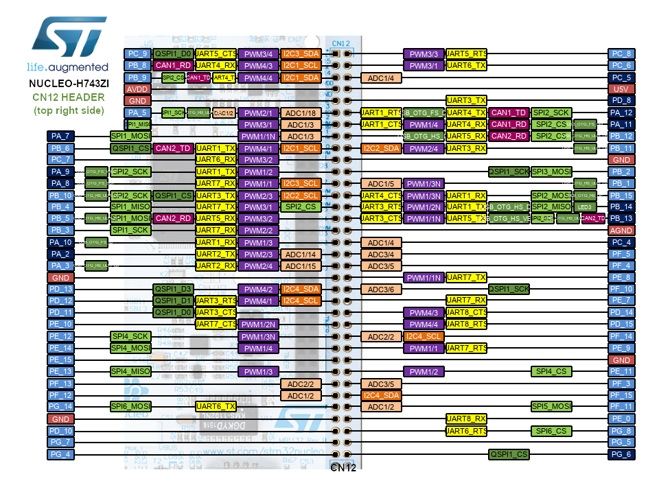
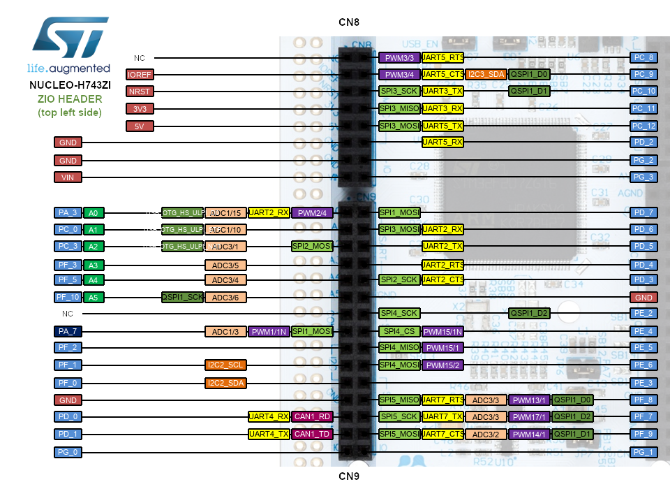
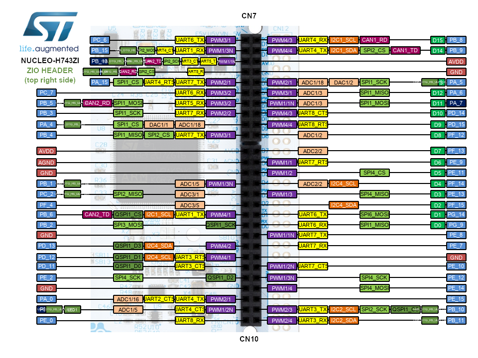
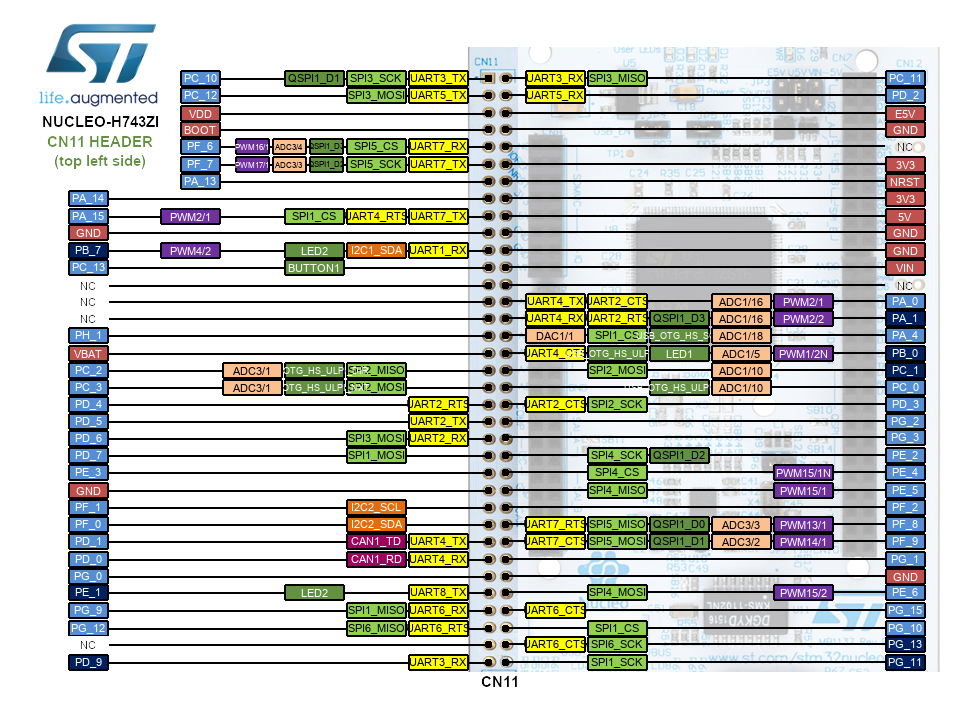
This page provides the complete Nucleo-H743ZI Pinout diagrams for the STM32 Nucleo-H743ZI development board. The Nucleo-H743ZI is based on the STM32H743ZIT6 microcontroller running at up to 480 MHz with 2MB flash and 1MB RAM. Diagrams include both Arduino / ZIO and Morpho header pin assignments with alternate function labels. These diagrams also apply to the Nucleo-H743ZI2, which is a hardware PCB revision of the H743ZI with identical pin assignments.
Click any image to view it full-size in a new tab.
Search by pin name (e.g. PA9, PG14) or by function name (e.g. USART1_TX, QSPI_BK1) across all four header diagrams. Data is sourced from ST’s official UM1974 Nucleo-144 User Manual and the STM32H743 pin database.
Note: the function list shown for each pin is that pin’s full MCU-level alternate-function capability — not every function listed is necessarily wired or labeled on this specific connector; the diagram’s own green/colored tags show only what ST has actually broken out at that position.
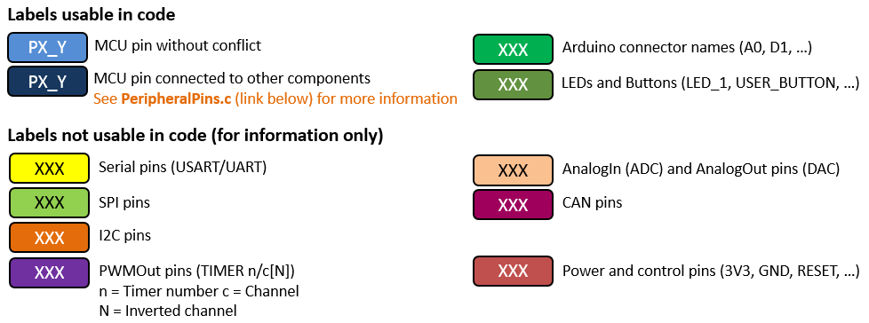
Pinout Legend
Arduino / ZIO Headers
Arduino / ZIO Header (Top Left — CN8 / CN9)
Arduino / ZIO Header (Top Right — CN7 / CN10)
Morpho Headers
Morpho Header (Top Left — CN11)
Morpho Header (Top Right — CN12)