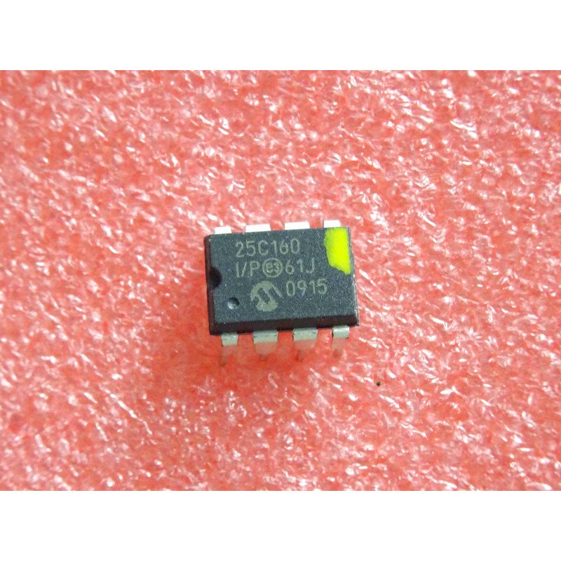
Overview
This STM32 DS3231 RTC tutorial reads and sets a DS3231 real-time clock over I2C on a NUCLEO-H753ZI and prints the day, date and time on a serial terminal. The AT24C32 EEPROM that sits on the same ZS-042 module remembers that the clock has already been set, so the firmware sets the clock once, from the time it was compiled, and never again after a reset or a power cycle unless you ask it to.
Setting an STM32 DS3231 RTC sounds trivial and is not: if the program sets the time at every start-up, every reset throws the clock back to the same moment. This project solves that with a small marker stored in the EEPROM, a single #define to force a new setting, and two small plain-C libraries, STM32_DS3231 for the clock and STM32_AT24C32 for the EEPROM. The ZS-042 module also has a battery charging circuit that is dangerous with a non-rechargeable coin cell at 5 V, so this tutorial powers the module from 3.3 V and explains why.
Related tutorials: if you want the time to come from the network instead, read STM32 FreeRTOS SNTP RTC Time Synchronization; the STM32 RTC Time Zone Conversion with Linux EPOCH Time tutorial covers turning epoch seconds into local time; and STM32 SPI EEPROM 25AA040A shows a different EEPROM, over SPI.
What You Will Learn
- How to wire a ZS-042 DS3231 module to a NUCLEO-H753ZI on I2C1, and why to power it from 3.3 V and not 5 V
- How the DS3231 stores the time as BCD in seven registers, and how the driver reads and sets them in one burst
- How to set the clock from the compiler’s
__DATE__and__TIME__, and what limits the accuracy - How to use the AT24C32 EEPROM on the same module to remember that the clock was set, with a marker that survives a power loss during its own write
- How the oscillator stop flag tells you whether the clock lost power, and when to clear it
- How the drivers retry transient I2C failures and then stop in
Error_Handler() - How to redraw a clock in place on a serial terminal, and why a
printfwithout a newline needsfflush(stdout)
Prerequisites
You should be comfortable creating and building an STM32CubeIDE project and have a working knowledge of C. No earlier experience with an STM32 DS3231 RTC is needed. Familiarity with I2C (SCL, SDA, pull-up resistors, 7-bit addresses) helps. Debug output is redirected to printf over USART1 through an external FTDI USB-to-serial adapter, per this site’s standard debug setup, and viewed in any serial terminal that understands ANSI escape sequences, at 19200 baud. The terminal is used only to look at the output, so nothing needs to be typed.
Materials List
- NUCLEO-H753ZI development board
- ZS-042 DS3231 real-time clock module with the AT24C32 EEPROM (a 5-pack from HiLetgo was used here)
- CR2032 coin cell for the module’s battery holder (the modules ship without one)
- FTDI USB-to-serial adapter, for USART1 debug output
- Breadboard and jumper wires
- USB cable for the Nucleo’s ST-LINK connector
Board Diagram
ZS-042 DS3231 Module
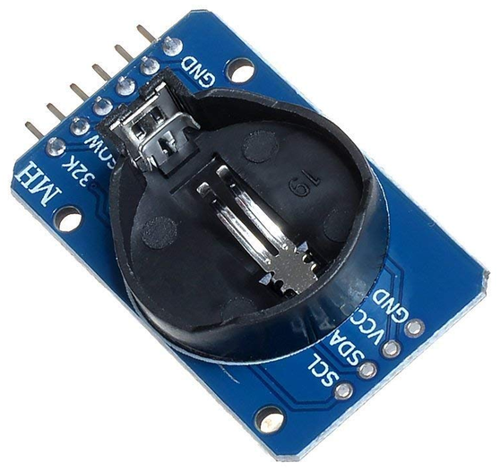
The ZS-042 is the usual choice for an STM32 DS3231 RTC project: a common, inexpensive breakout that carries a DS3231 real-time clock, an AT24C32 EEPROM, a coin-cell holder and a power LED. The DS3231 keeps the time with a temperature-compensated crystal oscillator, counts seconds, minutes, hours, the weekday, the date, the month and the year up to 2099, and keeps running from the coin cell when the main supply is off. The AT24C32 is a 32 Kbit (4096 byte) EEPROM that answers on the same two I2C wires.
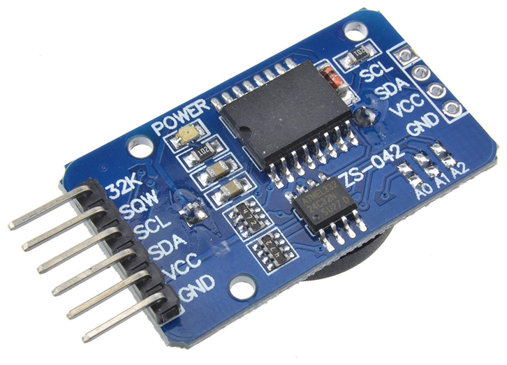
| ZS-042 pin | Function |
|---|---|
| 32K | 32.768 kHz square-wave output of the DS3231 (open-drain). Not used in this project |
| SQW | Interrupt or square-wave output of the DS3231 (open-drain, active low). Not used in this project |
| SCL | I2C clock, shared by the DS3231 and the EEPROM |
| SDA | I2C data, shared by the DS3231 and the EEPROM |
| VCC | Supply for both chips and for the module’s pull-up resistors. Use 3.3 V (see below) |
| GND | Ground |
The second, four-pin header (SCL, SDA, VCC, GND) carries the same signals so a second module can be chained. The solder pads A0, A1 and A2 select the EEPROM’s address; left open, they are pulled high and the EEPROM answers at 0x57. The DS3231 always answers at 0x68. The module has pull-up resistors on SCL and SDA (4.7 kΩ on the module used here), so you add none.
Power the Module from 3.3 V, not 5 V
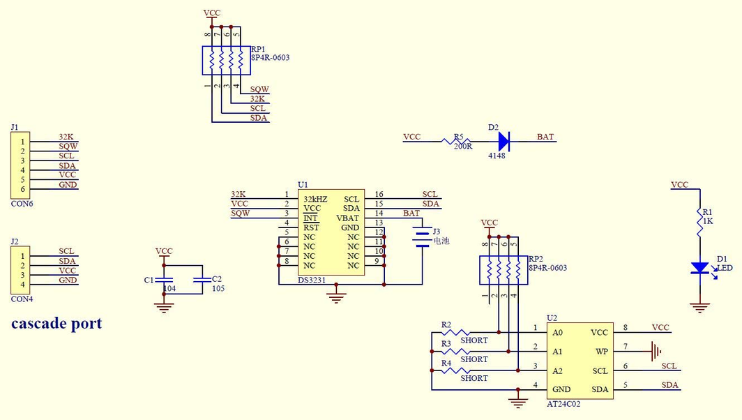
Use 3.3 V. The ZS-042 has no manufacturer datasheet; the schematic below, supplied by the seller, is the documentation for the board, and it shows two reasons not to run the module from 5 V:
- It charges the battery. The module has a charging path from VCC through a 200 Ω resistor (R5) and a 1N4148 diode (D2) to the battery pin. At 5 V the diode’s output is about 4.3 V, well above a CR2032’s roughly 3 V, so current flows into the cell. A CR2032 is not rechargeable and can leak or swell. At 3.3 V the diode’s output is about 2.6 V, below the cell, so the diode stays reverse-biased and nothing is charged. (If you must use 5 V, fit a rechargeable LIR2032 or remove the diode.)
- It puts 5 V on the I2C lines. The pull-up resistor network RP1 ties SCL, SDA, SQW and 32K to the module’s VCC, so at 5 V those lines idle at 5 V. Many MCU pins, and any other device on the bus, are not 5 V tolerant. At 3.3 V they idle at the MCU’s own logic level.
The DS3231 works from 2.3 V to 5.5 V and the AT24C32 also works at 3.3 V, so powering the STM32 DS3231 RTC module from 3.3 V loses nothing. The values in this paragraph come from the schematic, not from measurements of every board, so check yours before relying on them.
If the schematic is too small to read clearly, open the full-size image in a new tab and use Ctrl-Scroll to zoom in.
Datasheets for the two chips: Download the DS3231 Datasheet PDF file from Analog Devices and Download the AT24C32D Datasheet PDF file from Microchip. The EEPROM on many ZS-042 modules is marked 24C32N, an older Atmel part. Its AT24C32 datasheet differs in details such as the write cycle time, which is 10 ms maximum instead of 5 ms.
Project Structure
The STM32 DS3231 RTC project’s own files are one download and each of the two libraries is another, so the libraries can be shared with other projects (see Getting the Libraries below). After you unpack the source zip and the two library zips into one project folder the tree looks like this, with the library folders marked:
H753_CPP_I2C_DS3231_RTC_01/
├── STM32_DS3231/               <- from the STM32_DS3231 zip
│   ├── DS3231.c
│   ├── DS3231.h
│   ├── LICENSE
│   └── README.md
├── STM32_AT24C32/              <- from the STM32_AT24C32 zip
│   ├── AT24C32.c
│   ├── AT24C32.h
│   ├── LICENSE
│   └── README.md
├── Core/
│   ├── Inc/
│   │   └── main.h
│   └── Src/
│       └── main.c
├── H753_CPP_I2C_DS3231_RTC_01.ioc
├── H753_CPP_I2C_DS3231_RTC_01.pdf
├── H753_CPP_I2C_DS3231_RTC_01.txt
├── LICENSE
├── README.md
├── STM32H753ZITX_FLASH.ld
└── STM32H753ZITX_RAM.ld
Hardware Configuration / Pinouts
Overview
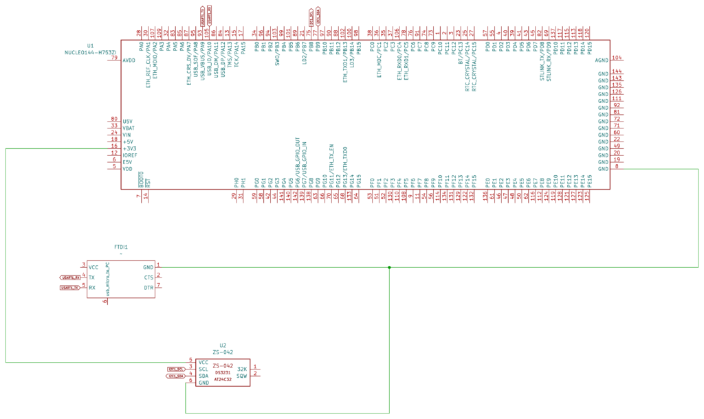
The STM32 DS3231 RTC project uses I2C1 for both chips on the module, and USART1 for the terminal. Both I2C devices share SCL and SDA and are told apart by their addresses: the DS3231 at 0x68 and the EEPROM at 0x57.
| Signal | Nucleo-H753ZI pin | Notes |
|---|---|---|
| ZS-042 VCC | 3V3 | Use 3.3 V, not 5 V (see above) |
| ZS-042 GND | GND | |
| ZS-042 SCL | PB8 (Arduino D15) | I2C1_SCL. The module already has the pull-up |
| ZS-042 SDA | PB9 (Arduino D14) | I2C1_SDA. The module already has the pull-up |
| ZS-042 SQW, 32K | not connected | Open-drain outputs, unused here |
| FTDI RX / TX | PA9 / PA10 | USART1_TX / USART1_RX, debug output at 19200 baud |
PB8 and PB9 are on the Zio connector CN7 of the Nucleo-144 boards, as Arduino D15 (I2C1_SCL) and D14 (I2C1_SDA). The NUCLEO-H753ZI pinout page shows where they are on this board.
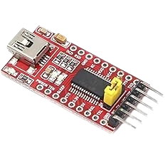
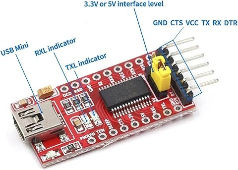
FTDI Pinouts
FTDI to USB Pinout from right to left
- Pin 1 – GND
- Pin 4 – TX
- Pin 5 – RX
- USB Mini – Connect to PC via USB cable
Make sure the jumper is set to 5V — the FTDI board is powered from the USB mini cable, and a computer’s USB port supplies 5 V. The FTDI TX goes to the Nucleo’s PA10 (USART1_RX) and the FTDI RX to PA9 (USART1_TX).
Schematic
If the schematic is too small to read clearly, open the full-size image in a new tab and use Ctrl-Scroll to zoom in. A vector (SVG) version is also available.
Pinouts & Configurations
The complete CubeMX pin assignment and peripheral configuration is captured in the IOC report below.
Project Setup
Create a new STM32CubeIDE project for this STM32 DS3231 RTC tutorial on the NUCLEO-H753ZI (the project uses plain C only). In the .ioc pinout view:
- Enable I2C1 on PB8 (SCL) and PB9 (SDA) in I2C mode, standard speed (100 kHz), 7-bit addressing. The module has the pull-up resistors, so leave the pins on No pull-up.
- Enable USART1 in Asynchronous mode on PA9/PA10 at 19200 baud for the
printfredirect. - Generate the code. The program needs no interrupts and no DMA.
Getting the Libraries
The source download contains only the STM32 DS3231 RTC project’s own files. The two libraries are shared code, so each is its own download, just like its own repository.
- Extract the source zip over the project, then extract the two library zips into the project root (the folder that contains
Core/). You should now haveSTM32_DS3231/andSTM32_AT24C32/next toCore/, exactly as in the Project Structure tree above. Let CubeIDE overwrite the files it generated. - In CubeIDE, right-click the project and choose Refresh (F5).
- Make each library folder a source folder: Project → Properties → C/C++ General → Paths and Symbols → Source Location → Add Folder, then tick
STM32_DS3231andSTM32_AT24C32. A source folder shows a small gear on its icon in the Project Explorer. - Open Project → Properties → C/C++ Build → Settings. Under both MCU GCC Compiler → Include paths and MCU G++ Compiler → Include paths, add
${workspace_loc:/${ProjName}/STM32_DS3231}and${workspace_loc:/${ProjName}/STM32_AT24C32}. Do this for both the Debug and Release configurations. The code includes the library headers by name, so these paths are required. - Build the project. If you see “DS3231.h: No such file or directory” (or the same for AT24C32.h), the include paths in step 4 are missing or were added to only one compiler or one configuration. If the build ends with “undefined reference to ds3231Init”, the folder in step 3 is not a source folder.
The libraries are also maintained as separate repositories, STM32_DS3231 and STM32_AT24C32. If you prefer git, clone them into the project root, or add them as submodules so each library keeps its own history.
Code Walkthrough
How the STM32 DS3231 RTC Project Fits Together
Three pieces cooperate, and each lives in its own place:
STM32_DS3231(library): reads and sets the clock, converts to and from Unix epoch seconds, and reports and clears the oscillator stop flag.STM32_AT24C32(library): reads and writes the EEPROM, splitting writes at the chip’s page boundaries and waiting for each write cycle to finish.main.c: the start-up sequence that decides whether to set the clock, the marker handling, and the terminal display.
The DS3231 Driver
Both libraries are plain C with one handle structure each, so they work from a C or a C++ project. They include the project’s main.h, which brings in the HAL. This is the public header of STM32_DS3231, with the error handling, wiring and thread-safety notes in its documentation comment:
/*
 * DS3231.h
 *
 * STM32 HAL driver for the Analog Devices (Maxim) DS3231 I2C real-time clock,
 * as found on the common ZS-042 breakout module.
 *
 * Written from the DS3231 datasheet: I2C address, timekeeping registers
 * 00h-06h, and the control/status register at 0Fh. It is an independent
 * implementation, not a port of anyone else's library.
 *
 *  Created on: Oct 7, 2026
 *      Author: johng
 */

#ifndef STM32_DS3231_DS3231_H_
#define STM32_DS3231_DS3231_H_

#include "main.h"
#include <stdbool.h>
#include <stdint.h>

#ifdef __cplusplus
extern "C" {
#endif

/**
 * @file DS3231.h
 * @brief Types, constants and function prototypes of the STM32_DS3231 driver.
 *
 * Every function is documented where it is defined, in DS3231.c.
 *
 * @par Error handling
 * A failed HAL I2C read or write is something the program cannot continue
 * from, but only some failures are worth retrying. A transient communication
 * failure (HAL_BUSY, HAL_TIMEOUT, or HAL_ERROR with an I2C error code for a
 * bus problem: bus error, arbitration lost, acknowledge failure, overrun or
 * timeout) is retried: the complete transaction is sent again, up to
 * DS3231_t::maxAttempts times in all. Any other failure, such as HAL_ERROR
 * from a bad parameter or a peripheral in the wrong state, cannot be fixed by
 * trying again and is not retried. Once the attempts are used up, or at once
 * for a failure that is not retried, the driver calls Error_Handler() from
 * main.h, which does not return. DS3231_t::lastStatus holds the HAL status of
 * the most recent failed attempt.
 *
 * Problems that are the caller's to handle are returned as a DS3231_Status_t
 * instead: a bad argument, a chip that does not answer or does not look like a
 * DS3231 in ds3231Init(), and time registers that hold an impossible date.
 *
 * @par Wiring
 * VCC, GND, SCL and SDA go to the MCU. The ZS-042 module has pull-up resistors
 * on SCL and SDA (and on SQW and 32K) tied to its own VCC, so no external
 * pull-ups are needed.
 *
 * @warning Power the ZS-042 from 3.3 V, not 5 V. (1) The module charges its
 * battery pin through a 200 ohm resistor and a diode from VCC; at 5 V that
 * pushes current into a non-rechargeable CR2032, which can leak or swell; at
 * 3.3 V the diode stays reverse-biased. (2) The pull-ups go to the module's
 * VCC, so at 5 V the I2C lines idle at 5 V, which many MCU pins and other
 * bus devices do not tolerate. Both chips work from 3.3 V.
 *
 * @par Thread safety and ISR safety
 * Not thread-safe and not ISR-safe. Every operation is a blocking HAL I2C
 * transaction on a peripheral handle that other code may share, with no lock,
 * and ds3231ClearOscillatorStopFlag() is a read followed by a write. A second
 * caller (another RTOS task, or an interrupt handler) that uses the same
 * I2C peripheral between those steps would interleave with this driver and
 * corrupt both transfers. Call the driver from one context, or put a mutex
 * around every use of the shared I2C handle. Do not call it from an interrupt
 * handler: the HAL calls block and use HAL_Delay() for the retry pause.
 */

/** 8-bit (write) I2C address of the DS3231: the 7-bit address 0x68 shifted left, as the HAL expects. */
#define DS3231_I2C_ADDRESS          (0x68U << 1)

/** Number of attempts used when ds3231Init() is given 0 for @c maxAttempts. */
#define DS3231_DEFAULT_MAX_ATTEMPTS 3U

/** Timeout, in milliseconds, of one HAL I2C transfer. */
#define DS3231_I2C_TIMEOUT_MS       100U

/** First year the driver accepts (the chip stores a two-digit year). */
#define DS3231_YEAR_MIN             2000U

/** Last year the driver accepts. */
#define DS3231_YEAR_MAX             2099U

/** Seconds from 1970-01-01 00:00:00 to 2000-01-01 00:00:00: the lowest epoch value the driver accepts. */
#define DS3231_EPOCH_MIN            946684800U

/** Seconds from 1970-01-01 00:00:00 to 2099-12-31 23:59:59: the highest epoch value the driver accepts. */
#define DS3231_EPOCH_MAX            4102444799U

/** Result of a driver function. */
typedef enum {
    DS3231_OK = 0,            /**< The call succeeded. */
    DS3231_ERR_PARAM,         /**< A pointer was NULL or a value was outside its valid range. */
    DS3231_ERR_NOT_FOUND,     /**< Nothing answered at the DS3231 address, or what answered is not a DS3231. */
    DS3231_ERR_INVALID_DATA,  /**< The time registers hold something that is not a valid date and time. */
    DS3231_ERR_BUS            /**< An I2C transfer failed for good. Only returned if Error_Handler() returns. */
} DS3231_Status_t;

/**
 * @brief A calendar date and time, always 24-hour clock.
 *
 * ds3231SetTime() ignores @c weekday and works it out from the date;
 * ds3231GetTime() fills it in the same way. The chip's own day-of-week
 * register is user-defined, so the driver never relies on it.
 */
typedef struct {
    uint16_t year;    /**< Full year, 2000 to 2099. */
    uint8_t  month;   /**< Month, 1 to 12. */
    uint8_t  day;     /**< Day of the month, 1 to 31 (limited by the month). */
    uint8_t  weekday; /**< Day of the week, 1 = Monday to 7 = Sunday. */
    uint8_t  hour;    /**< Hour, 0 to 23. */
    uint8_t  minute;  /**< Minute, 0 to 59. */
    uint8_t  second;  /**< Second, 0 to 59. */
} DS3231_TIME_t;

/** One DS3231 on one I2C bus. Fill it in with ds3231Init(); do not edit the members by hand. */
typedef struct {
    I2C_HandleTypeDef *hi2c;       /**< The HAL I2C handle the chip is on (from CubeMX, for example @c hi2c1). */
    uint8_t            maxAttempts; /**< Attempts per transaction before Error_Handler() is called. */
    HAL_StatusTypeDef  lastStatus;  /**< HAL status of the most recent failed attempt (HAL_OK if none yet). */
} DS3231_t;

DS3231_Status_t ds3231Init(DS3231_t *dev, I2C_HandleTypeDef *hi2c, uint8_t maxAttempts);
DS3231_Status_t ds3231GetTime(DS3231_t *dev, DS3231_TIME_t *time);
DS3231_Status_t ds3231SetTime(DS3231_t *dev, const DS3231_TIME_t *time);
DS3231_Status_t ds3231GetEpoch(DS3231_t *dev, uint32_t *epochSeconds);
DS3231_Status_t ds3231SetEpoch(DS3231_t *dev, uint32_t epochSeconds);
DS3231_Status_t ds3231IsOscillatorStopped(DS3231_t *dev, bool *stopped);
DS3231_Status_t ds3231ClearOscillatorStopFlag(DS3231_t *dev);

bool            ds3231IsTimeValid(const DS3231_TIME_t *time);
DS3231_Status_t ds3231TimeToEpoch(const DS3231_TIME_t *time, uint32_t *epochSeconds);
DS3231_Status_t ds3231EpochToTime(uint32_t epochSeconds, DS3231_TIME_t *time);

#ifdef __cplusplus
}
#endif

#endif /* STM32_DS3231_DS3231_H_ */The DS3231 keeps the time in seven registers starting at 0x00 (seconds, minutes, hours, weekday, date, month, year), each in binary-coded decimal. ds3231GetTime() reads all seven in one burst, which the chip freezes into a buffer so the values cannot change halfway through. It masks the century bit, checks that every field is valid BCD and in range, converts a clock found in 12-hour mode to 24-hour, and works the weekday out from the date instead of trusting the chip’s user-defined day register:
/**
 * @brief Read the current date and time.
 *
 * Reads the seven timekeeping registers in one burst, which the chip freezes into a
 * buffer so the values cannot change halfway through. A clock set to 12-hour mode by
 * other code is converted to 24-hour. The weekday is worked out from the date.
 *
 * @param dev  The driver handle, set up with ds3231Init().
 * @param time Receives the date and time.
 * @return DS3231_OK; DS3231_ERR_PARAM if a pointer is NULL; DS3231_ERR_INVALID_DATA if the
 *         registers do not hold a valid date and time (typical right after the first power-up,
 *         before the clock has ever been set; see ds3231IsOscillatorStopped()).
 */
DS3231_Status_t ds3231GetTime(DS3231_t *dev, DS3231_TIME_t *time)
{
    uint8_t raw[TIME_REG_COUNT];
    uint8_t hours;
    uint8_t month;
    uint8_t i;

    if (dev == NULL || time == NULL) {
        return DS3231_ERR_PARAM;
    }

    if (transfer(dev, false, REG_SECONDS, raw, TIME_REG_COUNT) != DS3231_OK) {
        return DS3231_ERR_BUS;
    }

    /* Mask the unused bits and the century bit, then make sure every field is BCD. */
    raw[0] &= 0x7FU;
    raw[1] &= 0x7FU;
    raw[4] &= 0x3FU;
    raw[5] &= 0x1FU;
    for (i = 0U; i < TIME_REG_COUNT; i++) {
        if (i == 2U || i == 3U) {
            continue; /* hours are checked below, the day-of-week register is not used */
        }
        if (!isBcd(raw[i])) {
            return DS3231_ERR_INVALID_DATA;
        }
    }

    if ((raw[2] & HOURS_12H_BIT) != 0U) {
        uint8_t hours12 = (uint8_t)(raw[2] & 0x1FU);

        if (!isBcd(hours12)) {
            return DS3231_ERR_INVALID_DATA;
        }
        hours12 = bcdToDec(hours12);
        if (hours12 < 1U || hours12 > 12U) {
            return DS3231_ERR_INVALID_DATA;
        }
        hours = (uint8_t)((hours12 % 12U) + (((raw[2] & HOURS_PM_BIT) != 0U) ? 12U : 0U));
    } else {
        if (!isBcd((uint8_t)(raw[2] & 0x3FU))) {
            return DS3231_ERR_INVALID_DATA;
        }
        hours = bcdToDec((uint8_t)(raw[2] & 0x3FU));
    }

    month = bcdToDec(raw[5]);

    time->second = bcdToDec(raw[0]);
    time->minute = bcdToDec(raw[1]);
    time->hour = hours;
    time->day = bcdToDec(raw[4]);
    time->month = month;
    time->year = (uint16_t)(DS3231_YEAR_MIN + bcdToDec(raw[6]));
    time->weekday = 0U;

    if (!ds3231IsTimeValid(time)) {
        return DS3231_ERR_INVALID_DATA;
    }
    time->weekday = weekdayOf(time->year, time->month, time->day);
    return DS3231_OK;
}ds3231SetTime() validates the date first (leap years included) and writes nothing if it is wrong. It writes the seven registers in one burst, in 24-hour mode with the century bit clear:
/**
 * @brief Set the date and time.
 *
 * Writes the seven timekeeping registers in one burst, in 24-hour mode with the century
 * bit clear, and writes the weekday worked out from the date. The oscillator stop flag is
 * not touched: call ds3231ClearOscillatorStopFlag() afterwards if the clock had stopped.
 *
 * @param dev  The driver handle, set up with ds3231Init().
 * @param time The date and time to set; the weekday member is ignored.
 * @return DS3231_OK; DS3231_ERR_PARAM if a pointer is NULL or the date and time are not
 *         valid (see ds3231IsTimeValid()). Nothing is written to the chip in that case.
 */
DS3231_Status_t ds3231SetTime(DS3231_t *dev, const DS3231_TIME_t *time)
{
    uint8_t raw[TIME_REG_COUNT];

    if (dev == NULL || !ds3231IsTimeValid(time)) {
        return DS3231_ERR_PARAM;
    }

    raw[0] = decToBcd(time->second);
    raw[1] = decToBcd(time->minute);
    raw[2] = decToBcd(time->hour);                 /* 12/24 bit left 0: 24-hour mode */
    raw[3] = weekdayOf(time->year, time->month, time->day);
    raw[4] = decToBcd(time->day);
    raw[5] = decToBcd(time->month);                /* century bit left 0 */
    raw[6] = decToBcd((uint8_t)(time->year - DS3231_YEAR_MIN));

    return transfer(dev, true, REG_SECONDS, raw, TIME_REG_COUNT);
}Setting the time does not touch the oscillator stop flag, which is bit 7 of the status register at 0x0F. The flag is set the first time power is applied and whenever the oscillator has stopped, so a set flag means the time may be wrong. Clearing it is a read followed by a write of the status register. The write sets the two alarm flag bits to 1, which the datasheet says leaves them unchanged, so an alarm that fires between the read and the write is not lost:
/**
 * @brief Clear the oscillator stop flag.
 *
 * Reads the status register and writes it back with OSF cleared and the 32 kHz output setting
 * kept. The two alarm flags are written as 1, which the datasheet says leaves them unchanged,
 * so an alarm that fires between the read and the write is not lost. The read followed by the
 * write is not atomic against other users of the same I2C bus (see the thread-safety note).
 *
 * @param dev The driver handle, set up with ds3231Init().
 * @return DS3231_OK, or DS3231_ERR_PARAM if @p dev is NULL.
 */
DS3231_Status_t ds3231ClearOscillatorStopFlag(DS3231_t *dev)
{
    uint8_t statusRegister;

    if (dev == NULL) {
        return DS3231_ERR_PARAM;
    }

    if (transfer(dev, false, REG_STATUS, &statusRegister, 1U) != DS3231_OK) {
        return DS3231_ERR_BUS;
    }

    statusRegister = (uint8_t)((statusRegister & STATUS_EN32KHZ) | STATUS_ALARM_FLAGS);
    return transfer(dev, true, REG_STATUS, &statusRegister, 1U);
}Retrying I2C Failures
A failed HAL call is not something to carry on from, but only some failures are worth repeating. isTransient() decides: busy, timeout, or a HAL error with a bus-error, arbitration, acknowledge, overrun or timeout code can be fixed by trying again; anything else cannot. transfer() repeats the whole transaction up to maxAttempts times (3 by default) and, when the attempts run out or the failure cannot be fixed, calls Error_Handler(), which does not return. Problems that are the caller’s to handle, such as a bad argument or a chip that does not answer in ds3231Init(), are returned as a status instead.
/**
 * @brief Decide whether a failed HAL I2C attempt is worth repeating.
 * @param hi2c   The I2C handle the attempt used.
 * @param status The HAL status the attempt returned (not HAL_OK).
 * @return true for a transient communication failure (HAL_BUSY, HAL_TIMEOUT, or
 *         HAL_ERROR with a bus-error, arbitration, acknowledge, overrun or timeout code),
 *         false for anything a second try cannot fix.
 */
static bool isTransient(I2C_HandleTypeDef *hi2c, HAL_StatusTypeDef status)
{
    if (status == HAL_BUSY || status == HAL_TIMEOUT) {
        return true;
    }
    if (status == HAL_ERROR) {
        return (HAL_I2C_GetError(hi2c) & I2C_TRANSIENT_ERRORS) != 0U;
    }
    return false;
}
/**
* @brief Read or write registers, retrying transient failures, and halt if it cannot succeed.
*
* The whole transaction (register address plus data) is sent again on each retry.
* When the attempts are used up, or at once for a failure that is not transient,
* the failure status is stored in DS3231_t::lastStatus and Error_Handler() is called.
*
* @param dev The driver handle, already set up by ds3231Init().
* @param write true to write @p buffer to the chip, false to read into it.
* @param reg The first register address.
* @param buffer Data to write, or space for the data read.
* @param length Number of bytes.
* @return DS3231_OK on success. Does not return on failure (Error_Handler()); DS3231_ERR_BUS
* is only returned if Error_Handler() ever returns.
*/
static DS3231_Status_t transfer(DS3231_t *dev, bool write, uint8_t reg, uint8_t *buffer, uint16_t length)
{
uint8_t attempt;
for (attempt = 1U; attempt <= dev->maxAttempts; attempt++) {
HAL_StatusTypeDef status;
if (write) {
status = HAL_I2C_Mem_Write(dev->hi2c, DS3231_I2C_ADDRESS, reg, I2C_MEMADD_SIZE_8BIT,
buffer, length, DS3231_I2C_TIMEOUT_MS);
} else {
status = HAL_I2C_Mem_Read(dev->hi2c, DS3231_I2C_ADDRESS, reg, I2C_MEMADD_SIZE_8BIT,
buffer, length, DS3231_I2C_TIMEOUT_MS);
}
if (status == HAL_OK) {
return DS3231_OK;
}
dev->lastStatus = status;
if (!isTransient(dev->hi2c, status)) {
break;
}
HAL_Delay(1);
}
Error_Handler();
return DS3231_ERR_BUS;
}The AT24C32 Driver
STM32_AT24C32 follows the same pattern. Its header documents the address pins, the write endurance and the thread-safety notes:
/*
 * AT24C32.h
 *
 * STM32 HAL driver for the Atmel/Microchip AT24C32 32 Kbit (4096 byte) I2C EEPROM,
 * as found on the common ZS-042 DS3231 breakout module.
 *
 * Written from the AT24C32D datasheet (DS20006047A): device address, 16-bit word
 * address, 32-byte page write, acknowledge polling and sequential read. It is an
 * independent implementation, not a port of anyone else's library.
 *
 *  Created on: Oct 7, 2026
 *      Author: johng
 */

#ifndef STM32_AT24C32_AT24C32_H_
#define STM32_AT24C32_AT24C32_H_

#include "main.h"
#include <stdint.h>

#ifdef __cplusplus
extern "C" {
#endif

/**
 * @file AT24C32.h
 * @brief Types, constants and function prototypes of the STM32_AT24C32 driver.
 *
 * Every function is documented where it is defined, in AT24C32.c.
 *
 * @par Error handling
 * A failed HAL I2C read or write is something the program cannot continue
 * from, but only some failures are worth retrying. A transient communication
 * failure (HAL_BUSY, HAL_TIMEOUT, or HAL_ERROR with an I2C error code for a
 * bus problem: bus error, arbitration lost, acknowledge failure, overrun or
 * timeout) is retried: the complete transaction is sent again, up to
 * AT24C32_t::maxAttempts times in all. Retrying is safe here because writing
 * the same bytes to the same address twice gives the same result. Any other
 * failure, such as HAL_ERROR from a bad parameter or a peripheral in the wrong
 * state, cannot be fixed by trying again and is not retried. A write cycle
 * that does not finish within AT24C32_WRITE_TIMEOUT_MS is also a failure. Once
 * the attempts are used up, or at once for a failure that is not retried, the
 * driver calls Error_Handler() from main.h, which does not return.
 * AT24C32_t::lastStatus holds the HAL status of the most recent failed attempt.
 *
 * Problems that are the caller's to handle are returned as an
 * AT24C32_Status_t instead: a bad argument, an address range that runs past
 * the end of the memory, and a chip that does not answer in at24c32Init().
 *
 * @par Wiring
 * On the ZS-042 module the EEPROM shares SCL and SDA with the DS3231, and its
 * address pins A0 to A2 are pulled up to VCC, so the chip answers at 0x57
 * (pass @c addressPins = 7 to at24c32Init()). Bridging the module's A0, A1 and
 * A2 solder pads ties the corresponding pin to ground and changes the address.
 * The write-protect pin is tied to ground on the module, so writes are always
 * enabled.
 *
 * @warning Power the ZS-042 from 3.3 V, not 5 V: at 5 V the module's battery
 * charging circuit pushes current into a non-rechargeable CR2032, and its
 * pull-ups put 5 V on SCL and SDA. See the STM32_DS3231 documentation for the
 * details. The AT24C32 works from 3.3 V.
 *
 * @par Thread safety and ISR safety
 * Not thread-safe and not ISR-safe. A write is several blocking HAL I2C
 * transactions in a row (one per page, each followed by acknowledge polling)
 * on a peripheral handle that other code may share, with no lock. A second
 * caller (another RTOS task, or an interrupt handler) that uses the same I2C
 * peripheral between those steps would interleave with this driver and
 * corrupt both transfers. Call the driver from one context, or put a mutex
 * around every use of the shared I2C handle. Do not call it from an interrupt
 * handler: the HAL calls block and the write wait polls HAL_GetTick().
 *
 * @par Endurance
 * The datasheet guarantees about one million write cycles per byte at 25 degrees
 * Celsius. Do not rewrite the same location in a fast loop.
 */

/** Size of the memory in bytes (32 Kbit). */
#define AT24C32_SIZE_BYTES          4096U

/** Size of one write page in bytes. A page write never crosses a page boundary. */
#define AT24C32_PAGE_SIZE           32U

/** Highest value of the A2 A1 A0 address pins (they select 0x50 to 0x57). */
#define AT24C32_MAX_ADDRESS_PINS    7U

/** Number of attempts used when at24c32Init() is given 0 for @c maxAttempts. */
#define AT24C32_DEFAULT_MAX_ATTEMPTS 3U

/** Timeout, in milliseconds, of one HAL I2C transfer. */
#define AT24C32_I2C_TIMEOUT_MS      100U

/**
 * Longest time, in milliseconds, to wait for a page write to finish. The datasheet
 * gives 5 ms maximum (AT24C32D); older AT24C32 revisions give 10 ms.
 */
#define AT24C32_WRITE_TIMEOUT_MS    20U

/** Result of a driver function. */
typedef enum {
    AT24C32_OK = 0,           /**< The call succeeded. */
    AT24C32_ERR_PARAM,        /**< A pointer was NULL, or a value or address range was invalid. */
    AT24C32_ERR_NOT_FOUND,    /**< Nothing answered at the EEPROM address. */
    AT24C32_ERR_BUS           /**< An I2C transfer failed for good. Only returned if Error_Handler() returns. */
} AT24C32_Status_t;

/** One AT24C32 on one I2C bus. Fill it in with at24c32Init(); do not edit the members by hand. */
typedef struct {
    I2C_HandleTypeDef *hi2c;        /**< The HAL I2C handle the chip is on (from CubeMX, for example @c hi2c1). */
    uint16_t           deviceAddress; /**< 8-bit (write) I2C address: 0x50 plus the address pins, shifted left. */
    uint8_t            maxAttempts;   /**< Attempts per transaction before Error_Handler() is called. */
    HAL_StatusTypeDef  lastStatus;    /**< HAL status of the most recent failed attempt (HAL_OK if none yet). */
} AT24C32_t;

AT24C32_Status_t at24c32Init(AT24C32_t *dev, I2C_HandleTypeDef *hi2c, uint8_t addressPins, uint8_t maxAttempts);
AT24C32_Status_t at24c32Read(AT24C32_t *dev, uint16_t memAddress, uint8_t *data, uint16_t length);
AT24C32_Status_t at24c32Write(AT24C32_t *dev, uint16_t memAddress, const uint8_t *data, uint16_t length);

#ifdef __cplusplus
}
#endif

#endif /* STM32_AT24C32_AT24C32_H_ */Two properties of the EEPROM shape the driver. A page write that crosses a 32-byte page boundary wraps around inside the page and overwrites the start of that page, so at24c32Write() splits the data at page boundaries. And after each page the chip is busy writing internally and does not acknowledge its address, so the driver polls for the acknowledge (up to 20 ms; the datasheet allows 5 ms for the AT24C32D and 10 ms for older revisions) before it goes on, which means the data is stored when the function returns:
/**
 * @brief Wait for the internal write cycle that follows a page write to finish.
 *
 * Uses acknowledge polling: the chip does not acknowledge its address while it is writing, so the
 * address is sent again until it is acknowledged or AT24C32_WRITE_TIMEOUT_MS has passed. If it never
 * finishes, the last status is stored in AT24C32_t::lastStatus and Error_Handler() is called.
 *
 * @param dev The driver handle, already set up by at24c32Init().
 * @return AT24C32_OK once the chip answers. Does not return if the wait times out (Error_Handler());
 *         AT24C32_ERR_BUS is only returned if Error_Handler() ever returns.
 */
static AT24C32_Status_t waitWriteComplete(AT24C32_t *dev)
{
    uint32_t start = HAL_GetTick();
    HAL_StatusTypeDef status;

    do {
        status = HAL_I2C_IsDeviceReady(dev->hi2c, dev->deviceAddress, 1U, AT24C32_I2C_TIMEOUT_MS);
        if (status == HAL_OK) {
            return AT24C32_OK;
        }
    } while ((HAL_GetTick() - start) <= AT24C32_WRITE_TIMEOUT_MS);

    dev->lastStatus = status;
    Error_Handler();
    return AT24C32_ERR_BUS;
}
/**
* @brief Write bytes to the memory.
*
* The data is split at page boundaries (32 bytes), because a page write that crosses a boundary
* wraps around inside the page and overwrites the start of that page. Each page is written, then
* the function waits for the chip's internal write cycle to finish (acknowledge polling) before the
* next one, so when the function returns the data is stored. A range that would run past the end of
* the memory is rejected before anything is written.
*
* @param dev The driver handle, set up with at24c32Init().
* @param memAddress First address to write, 0 to 4095.
* @param data The bytes to write.
* @param length Number of bytes to write.
* @return AT24C32_OK; AT24C32_ERR_PARAM if a pointer is NULL, @p length is 0, or the range
* @p memAddress to @p memAddress + @p length - 1 is not inside 0 to 4095.
*/
AT24C32_Status_t at24c32Write(AT24C32_t *dev, uint16_t memAddress, const uint8_t *data, uint16_t length)
{
if (dev == NULL || data == NULL || length == 0U ||
memAddress >= AT24C32_SIZE_BYTES || length > (AT24C32_SIZE_BYTES - memAddress)) {
return AT24C32_ERR_PARAM;
}
while (length > 0U) {
uint8_t page[AT24C32_PAGE_SIZE];
uint16_t room = (uint16_t)(AT24C32_PAGE_SIZE - (memAddress % AT24C32_PAGE_SIZE));
uint16_t chunk = (length < room) ? length : room;
memcpy(page, data, chunk); /* HAL takes a non-const pointer; a copy avoids casting const away */
if (transfer(dev, true, memAddress, page, chunk) != AT24C32_OK ||
waitWriteComplete(dev) != AT24C32_OK) {
return AT24C32_ERR_BUS;
}
memAddress = (uint16_t)(memAddress + chunk);
data += chunk;
length = (uint16_t)(length - chunk);
}
return AT24C32_OK;
}main.c: Settings
Everything below lives inside the CubeMX USER CODE blocks, so regenerating the project does not remove it. The includes and the settings first. FORCE_SET_TIME is 0 in normal use; SET_TIME_OFFSET_SECONDS compensates for the delay between compiling and running:
#include <stdio.h>
#include <stdbool.h>
#include <string.h>
#include "DS3231.h"
#include "AT24C32.h"/** Terminal row of the date line of the clock (the time is on the row below); the start-up messages above it stay put while the clock redraws in place. */
#define CLOCK_ROW 11
/** ANSI escape sequence that hides the terminal cursor so it does not flicker on the clock line. */
#define ANSI_HIDE_CURSOR "\x1b[?25l"
/** 1 = at start-up, set the DS3231 from the time this file was compiled (__DATE__ and __TIME__) even
* though the EEPROM marker says it was set before. Build and run once with it at 1, then set it back
* to 0 and rebuild, or every reset sets the clock back to the old build time. With 0 the clock is set
* only the first time, when the EEPROM holds no marker. */
#define FORCE_SET_TIME 0
/** Seconds added to the build time to cover the delay between compiling this file and the program
* starting (compile, link, flash). Measure the error once and enter it here; 0 is fine to start with. */
#define SET_TIME_OFFSET_SECONDS 0
/**
* @name Clock marker
* The "clock already set" marker kept in the AT24C32: a magic number followed by its bitwise inverse,
* 8 bytes at address 0. A write cut short by a power loss leaves a pair that does not match, which is
* read as "no marker". See startClock(), readClockMarker() and writeClockMarker().
* @{
*/
/** EEPROM address of the clock marker. */
#define CLOCK_MARKER_ADDRESS 0U
/** First half of the marker: the magic number (the ASCII letters "DS32"). The second half is its bitwise inverse. */
#define CLOCK_MARKER_MAGIC 0x44533332U
/** Size of the marker in bytes: the magic number plus its inverse, 4 bytes each. */
#define CLOCK_MARKER_SIZE 8U
/** @} */Every setting in that block, with its default:
| Macro | Default | What it does |
|---|---|---|
FORCE_SET_TIME | 0 | 1 sets the clock from the build time at start-up even though the EEPROM marker says it was set before. Set it back to 0 and rebuild afterwards |
SET_TIME_OFFSET_SECONDS | 0 | Seconds added to the build time to cover the delay between compiling and running |
CLOCK_ROW | 11 | Terminal row of the date line of the clock; the time is on the row below |
ANSI_HIDE_CURSOR | "\x1b[?25l" | Escape sequence that hides the terminal cursor so it does not flicker on the clock |
CLOCK_MARKER_ADDRESS | 0 | EEPROM address of the “clock already set” marker |
CLOCK_MARKER_MAGIC | 0x44533332 | First half of the marker (the ASCII letters “DS32”); the second half is its bitwise inverse |
CLOCK_MARKER_SIZE | 8 | Size of the marker in bytes |
The two driver handles and two string arrays for the day and month names. The driver numbers the weekday 1 (Monday) to 7 (Sunday), so index 0 of each array is unused:
/** The DS3231 on I2C1, set up by ds3231Init(). */
static DS3231_t rtc;

/** The AT24C32 EEPROM on I2C1 (address pins all high, 0x57), set up by at24c32Init(). */
static AT24C32_t eeprom;

/** Day names, indexed by the driver's weekday number: 1 = Monday to 7 = Sunday. Index 0 is unused. */
static const char *const dayNames[8] =
{
	"", "Monday", "Tuesday", "Wednesday", "Thursday", "Friday", "Saturday", "Sunday"
};

/** Month names, indexed by month number 1 to 12. Index 0 is unused. */
static const char *const monthNames[13] =
{
	"", "January", "February", "March", "April", "May", "June",
	"July", "August", "September", "October", "November", "December"
};main.c: The STM32 DS3231 RTC Start-Up Sequence
After the CubeMX peripheral init, main() prints a title, starts both chips, and calls startClock(). If either chip does not answer, the program prints the HAL status and the I2C error code and stops in Error_Handler():
  printf("\x1b[2J\x1b[H");	// Clear the dumb terminal screen
  printf(ANSI_HIDE_CURSOR);
  printf("\x1b[1mDS3231 real-time clock\x1b[0m\r\n-----------------------\r\n\r\n");
  fflush(stdout);	// no newline in the sequence, so push it out now

  if (ds3231Init(&rtc, &hi2c1, 0) != DS3231_OK) {
    printf("DS3231 not found on I2C1 (HAL status %d, I2C error 0x%02lX)\r\n",
           (int)rtc.lastStatus, (unsigned long)HAL_I2C_GetError(&hi2c1));
    Error_Handler();
  }

  if (at24c32Init(&eeprom, &hi2c1, 7, 0) != AT24C32_OK) {
    printf("AT24C32 EEPROM not found on I2C1 (HAL status %d, I2C error 0x%02lX)\r\n",
           (int)eeprom.lastStatus, (unsigned long)HAL_I2C_GetError(&hi2c1));
    Error_Handler();
  }

startClock();The main loop redraws the clock once a second:
  while (1)
  {
    printTime();
    HAL_Delay(1000);
}These are the helper functions. startClock() is the decision: with no marker in the EEPROM, or with FORCE_SET_TIME at 1, it sets the clock from the build time, and only after that succeeds does it write the marker and read it back. A marker is 8 bytes at EEPROM address 0: a magic number followed by its bitwise inverse, so a write cut short by a power loss leaves a pair that does not match and counts as “no marker”. With a marker found, the clock is left alone, and a warning is printed if the oscillator stopped since the clock was set:
/**
 * @brief  Report whether the DS3231 oscillator stop flag is set.
 *
 * A set flag means the oscillator has stopped since the flag was last cleared (first power-up, or
 * both VCC and the battery were too low), so the stored time cannot be trusted.
 * Halts through Error_Handler() if the status register cannot be read.
 * @retval true if the oscillator stop flag is set, false if it is clear.
 */
static bool reportOscillator(void)
{
	bool stopped = false;

	if (ds3231IsOscillatorStopped(&rtc, &stopped) != DS3231_OK) {
		printf("Could not read the DS3231 status register\r\n");
		Error_Handler();
		return false;
	}

	if (stopped) {
		printf("Oscillator : stop flag SET, the time is not valid until the clock is set\r\n");
	} else {
		printf("Oscillator : stop flag clear, the time is valid\r\n");
	}
	return stopped;
}

/**
 * @brief  Convert the compile date and time (__DATE__ and __TIME__) to a DS3231_TIME_t.
 *
 * __DATE__ looks like "Oct  8 2026" and __TIME__ like "22:50:47"; both are the local time of the
 * computer that compiled this file. The weekday member is not filled in (ds3231SetTime() works it out).
 * @param  time Receives the build date and time.
 * @retval true if both strings were parsed into a valid date and time, false otherwise.
 */
static bool parseBuildTime(DS3231_TIME_t *time)
{
	static const char months[] = "JanFebMarAprMayJunJulAugSepOctNovDec";
	const char *date = __DATE__;	/* "Mmm dd yyyy", day padded with a space */
	const char *clock = __TIME__;	/* "hh:mm:ss" */
	const char *found = NULL;
	uint8_t i;

	for (i = 0U; i < 12U; i++) {
		if (strncmp(&months[i * 3U], date, 3U) == 0) {
			found = &months[i * 3U];
			time->month = (uint8_t)(i + 1U);
		}
	}
	if (found == NULL) {
		return false;
	}

	time->day = (uint8_t)(((date[4] == ' ') ? 0 : (date[4] - '0')) * 10 + (date[5] - '0'));
	time->year = (uint16_t)((date[7] - '0') * 1000 + (date[8] - '0') * 100 + (date[9] - '0') * 10 + (date[10] - '0'));
	time->hour = (uint8_t)((clock[0] - '0') * 10 + (clock[1] - '0'));
	time->minute = (uint8_t)((clock[3] - '0') * 10 + (clock[4] - '0'));
	time->second = (uint8_t)((clock[6] - '0') * 10 + (clock[7] - '0'));
	time->weekday = 0U;

	return ds3231IsTimeValid(time);
}

/**
 * @brief  Set the DS3231 to the build time plus SET_TIME_OFFSET_SECONDS and clear the oscillator stop flag.
 *
 * The chip then holds the local time of the computer that compiled this file (no time-zone conversion).
 * Halts through Error_Handler() if the build time cannot be used or a write fails.
 */
static void setClockFromBuildTime(void)
{
	DS3231_TIME_t time;
	uint32_t epoch;

	if (!parseBuildTime(&time) || ds3231TimeToEpoch(&time, &epoch) != DS3231_OK ||
			ds3231EpochToTime((uint32_t)((int32_t)epoch + SET_TIME_OFFSET_SECONDS), &time) != DS3231_OK) {
		printf("The build time cannot be used to set the clock\r\n");
		Error_Handler();
		return;
	}

	if (ds3231SetTime(&rtc, &time) != DS3231_OK || ds3231ClearOscillatorStopFlag(&rtc) != DS3231_OK) {
		printf("Setting the DS3231 failed\r\n");
		Error_Handler();
		return;
	}

	printf("Clock      : set to the build time %04d-%02d-%02d %02d:%02d:%02d (offset %d s)\r\n",
			(int)time.year, (int)time.month, (int)time.day,
			(int)time.hour, (int)time.minute, (int)time.second, (int)SET_TIME_OFFSET_SECONDS);
}

/**
 * @brief  Tell whether the EEPROM holds the "clock already set" marker.
 *
 * The marker is CLOCK_MARKER_MAGIC followed by its bitwise inverse; anything else, including a half
 * written marker, counts as not found. Halts through Error_Handler() if the EEPROM cannot be read.
 * @retval true if a valid marker is stored, false if not.
 */
static bool readClockMarker(void)
{
	uint8_t raw[CLOCK_MARKER_SIZE];
	uint32_t magic;
	uint32_t inverse;

	if (at24c32Read(&eeprom, CLOCK_MARKER_ADDRESS, raw, sizeof(raw)) != AT24C32_OK) {
		printf("Could not read the clock marker from the EEPROM\r\n");
		Error_Handler();
		return false;
	}

	memcpy(&magic, &raw[0], sizeof(magic));
	memcpy(&inverse, &raw[4], sizeof(inverse));
	return (magic == CLOCK_MARKER_MAGIC) && (inverse == (uint32_t)~CLOCK_MARKER_MAGIC);
}

/**
 * @brief  Store the "clock already set" marker in the EEPROM and read it back to check it.
 *
 * Halts through Error_Handler() if the write fails or the marker does not read back as valid.
 */
static void writeClockMarker(void)
{
	uint8_t raw[CLOCK_MARKER_SIZE];
	uint32_t magic = CLOCK_MARKER_MAGIC;
	uint32_t inverse = (uint32_t)~CLOCK_MARKER_MAGIC;

	memcpy(&raw[0], &magic, sizeof(magic));
	memcpy(&raw[4], &inverse, sizeof(inverse));

	if (at24c32Write(&eeprom, CLOCK_MARKER_ADDRESS, raw, sizeof(raw)) != AT24C32_OK || !readClockMarker()) {
		printf("Writing the clock marker to the EEPROM failed\r\n");
		Error_Handler();
	}
}

/**
 * @brief  Decide at start-up whether to set the clock, and do it.
 *
 * With no marker in the EEPROM (first run on this board) or with FORCE_SET_TIME at 1, the clock is set
 * from the build time and the marker is written after that succeeded, so a failure leaves no marker.
 * Otherwise the clock is left alone; if the oscillator stop flag is set anyway the clock lost power,
 * and a message says to set FORCE_SET_TIME to 1.
 */
static void startClock(void)
{
	bool stopped = reportOscillator();
	bool markerFound = readClockMarker();

	if (FORCE_SET_TIME) {
		printf("EEPROM     : FORCE_SET_TIME is 1, setting the clock\r\n");
	} else if (markerFound) {
		printf("EEPROM     : marker found, the clock was set before\r\n");
		printf("Clock      : left alone\r\n");
		if (stopped) {
			printf("Warning    : the oscillator stopped since the clock was set.\r\n");
			printf("             Set FORCE_SET_TIME to 1 and rebuild to set it again.\r\n");
		}
		return;
	} else {
		printf("EEPROM     : no marker, first run on this board\r\n");
	}

	setClockFromBuildTime();
	writeClockMarker();
	printf("EEPROM     : marker written\r\n");

	if (FORCE_SET_TIME) {
		printf("Reminder   : set FORCE_SET_TIME to 0 and rebuild, or every reset\r\n");
		printf("             sets the clock back to this build time.\r\n");
	}
}

/**
 * @brief  Read the DS3231 and redraw the day, date and time on two terminal lines, for example
 *         "Wednesday, October 7, 2026" above a bold "23:30:58".
 *
 * Moves the cursor to row CLOCK_ROW (date) and the row below (time) and clears each line before printing,
 * so the clock updates in place instead of scrolling. Prints a message on that line instead when the registers hold no valid
 * time yet. Flushes stdout after each redraw: the line has no newline, and stdout is line-buffered, so
 * without the flush the text would sit in the buffer instead of appearing on the terminal. Halts through
 * Error_Handler() if the read fails.
 */
static void printTime(void)
{
	DS3231_TIME_t now;
	DS3231_Status_t status = ds3231GetTime(&rtc, &now);

	if (status == DS3231_ERR_INVALID_DATA) {
		printf("\x1b[%d;1H\x1b[K  The DS3231 does not hold a valid time yet\x1b[%d;1H\x1b[K", CLOCK_ROW, CLOCK_ROW + 1);
		fflush(stdout);
		return;
	}
	if (status != DS3231_OK) {
		printf("ds3231GetTime failed, status %d\r\n", (int)status);
		Error_Handler();
		return;
	}

	if (now.weekday < 1U || now.weekday > 7U || now.month < 1U || now.month > 12U) {
		printf("\x1b[%d;1H\x1b[K  The DS3231 returned a date that cannot be named\x1b[%d;1H\x1b[K", CLOCK_ROW, CLOCK_ROW + 1);
		fflush(stdout);
		return;
	}

	printf("\x1b[%d;1H\x1b[K  %s, %s %d, %04d\x1b[%d;1H\x1b[K  \x1b[1m%02d:%02d:%02d\x1b[0m",
			CLOCK_ROW, dayNames[now.weekday], monthNames[now.month], (int)now.day, (int)now.year,
			CLOCK_ROW + 1, (int)now.hour, (int)now.minute, (int)now.second);
	fflush(stdout);
}How the Build Time Is Used
parseBuildTime() turns the compiler’s __DATE__ (“Oct 8 2026”) and __TIME__ (“22:50:47”) into a date and time, and setClockFromBuildTime() adds SET_TIME_OFFSET_SECONDS and writes it to the DS3231. Three consequences are worth knowing:
- The chip holds the local time of the computer that compiled
main.c. There is no time-zone conversion. - The time is when
main.cwas compiled, so the clock is behind by the compile, link and flash delay, a few seconds. Measure the error once and enter it inSET_TIME_OFFSET_SECONDS. - Do not flash an old build with
FORCE_SET_TIMEat 1 later: the build time is old, so it would set a stale time.
Things to Know
- Forcing a new setting. Set
FORCE_SET_TIMEto 1, build, run once, then set it back to 0 and rebuild. Left at 1, every reset sets the clock back to that build time. - Lost power. If the coin cell is missing or flat and the module loses power, the DS3231 sets the oscillator stop flag and the clock is wrong. The marker is still in the EEPROM, so the firmware leaves the clock alone and prints a warning telling you to use
FORCE_SET_TIME. This warning path is in the code but is not shown in this tutorial’s test runs. - The coin cell and 5 V. Do not power the module from 5 V with a non-rechargeable cell fitted; see the section above.
- Not thread-safe. Both libraries make blocking HAL I2C calls on a shared handle with no lock, and some operations are several steps in a row, so call them from one thread and never from an interrupt handler.
- EEPROM wear. The marker is written once. The datasheet allows about a million write cycles per byte.
- A
printfwithout a newline needsfflush(stdout). The clock line is redrawn in place and has no newline, and CubeIDE’sstdoutis line-buffered, so without the flush the text sits in the buffer and the clock appears late or in bursts.
Running It: STM32 DS3231 RTC on the Board
First run
On a board whose EEPROM holds no marker, the first run of the STM32 DS3231 RTC firmware sets the clock and writes the marker.
On a brand-new module the Oscillator line reads stop flag SET, the time is not valid until the clock is set, because the DS3231 sets that flag the first time power is applied. The firmware then prints no marker, first run on this board on the EEPROM line, sets the clock to the build time, prints marker written, and starts showing the clock. The output otherwise matches the forced run in the next section, except that the two Reminder lines appear only when FORCE_SET_TIME is 1.
Forcing a new setting
To set the clock again, set FORCE_SET_TIME to 1, build and run once. The firmware sets the clock to the build time, writes the marker again, and reminds you to turn the define off. This is the output of such a run:
DS3231 real-time clock
-----------------------

Oscillator : stop flag clear, the time is valid
EEPROM     : FORCE_SET_TIME is 1, setting the clock
Clock      : set to the build time 2026-10-07 23:42:00 (offset 0 s)
EEPROM     : marker written
Reminder   : set FORCE_SET_TIME to 0 and rebuild, or every reset
             sets the clock back to this build time.

  Wednesday, October 7, 2026
23:42:00Set FORCE_SET_TIME back to 0 and rebuild straight away. If you flash the forced build and leave it, every power-up sets the clock back to that same build time, which is exactly what the reminder line says. That is easy to do by accident: a board that seems to lose the time on every power cycle is often still running a forced build.
Normal run
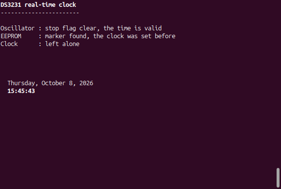
Build the STM32 DS3231 RTC project with FORCE_SET_TIME at 0, flash and open a serial terminal at 19200 baud. The firmware finds the marker, leaves the clock alone, and redraws the day, date and time once a second (the time is shown in bold):
DS3231 real-time clock
-----------------------

Oscillator : stop flag clear, the time is valid
EEPROM     : marker found, the clock was set before
Clock      : left alone


  Wednesday, October 7, 2026
23:39:11Reset the board, or unplug and replug its power: the clock keeps running from the coin cell, the marker is found, and the time carries on without jumping back.
USART1 Output
This is how the serial output looks in a terminal at 19200 baud on a normal run: the status lines stay where they were printed and only the day, date and time are redrawn once a second, with the time in bold.
Project Downloads
The complete project source code used in this tutorial is available for download. This includes all necessary files to build and run the project, along with supporting documentation.
- Full STM32CubeIDE Project (Source + Configuration)
- Doxygen Documentation (docs/html/index.html)
- Supporting Files: the STM32_DS3231 and STM32_AT24C32 libraries, one zip each (see Getting the Libraries above)
Documentation
This project includes full Doxygen-generated documentation for all custom source files.
The documentation is generated from the project source and both libraries in a single Doxygen run. It is included in the Doxygen documentation download above and can be viewed locally by opening:
H753_CPP_I2C_DS3231_RTC_01/docs/html/index.htmlin a web browser.
The documentation provides detailed descriptions of functions, data structures, and module interactions to assist with understanding and extending the STM32 DS3231 RTC project.
If you have questions or run into trouble getting the boards programmed and talking to each other, post in the Tutorial Support forum and I will work through it with you. If project source is not linked in the tutorial, it may be available on request — use the email contact option in the site footer.