Overview
This tutorial covers STM32 RA8875 TFT LCD 7 inch display interfacing using an STM32 microcontroller. The RA8875 communicates over a 2-wire SPI interface and provides hardware acceleration for drawing graphics including lines, rectangles, triangles, ellipses, and rounded rectangles, along with a built-in English/European font set. Its 768KB of internal RAM allows it to buffer the display efficiently even over SPI. To enable compatibility with existing Arduino libraries, the Adafruit RA8875 and Adafruit GFX libraries were ported to use STM32 HAL function calls. This tutorial also builds on the C and C++ integration approach covered in STM32 C++ Code – Using C++ with STM32CubeIDE.
Materials List
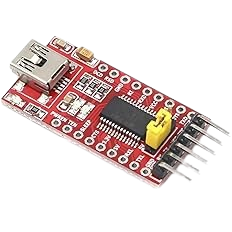
- FTDI to USB
- NUCLEO-F439ZI
- Breadboards Kit Include 2PCS 830 Point 2PCS 400 Point Solderless Breadboards
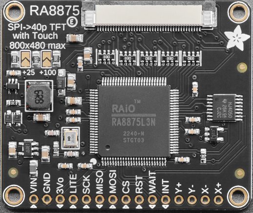
- RA8875 Driver Board for 40-pin TFT Touch Displays – 800×480 Max
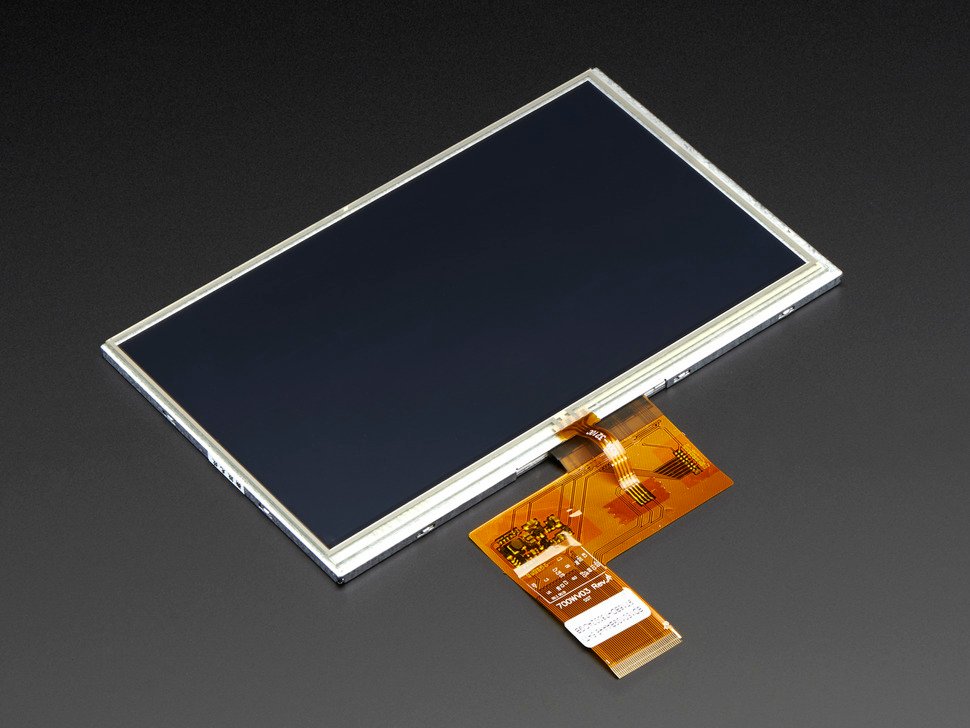
- 7.0″ 40-pin TFT Display – 800×480 with Touchscreen
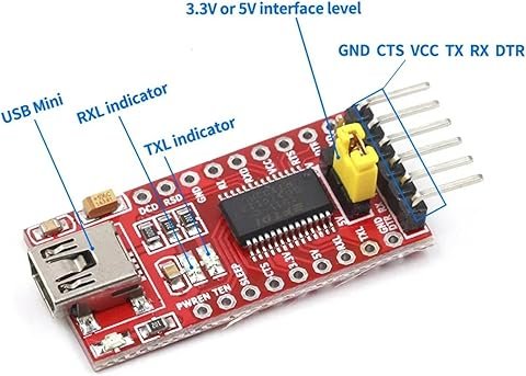
FTDI Pinouts
FTDI to USB Pinout from right to left
- Pin 1 – GND
- Pin 2 – CTS
- Pin 3 – VCC
- Pin 4 – TX
- Pin 5 – RX
- Pin 6 – DTR
- USB Mini – Connect to PC via USB cable
Make sure the jumper is set for 5v or 3v which ever is being used to power the FTDI device. If we look below at the schematic, it is showing in this case as 5v.
Adafruit RA8875 Pinouts

| RS8875 | Nucleo-F439 |
| VIN | 5V |
| GND | GND |
| 3Vo | Not Connected |
| LITE | Not Connected |
| SCK | PA5 |
| MISO | PA6 |
| MOSI | PB5 |
| CS | PG1 |
| RST | PG11 |
| WAIT | PG10 |
| INT | Not Connected |
| Y+ | Not Connected |
| Y- | Not Connected |
| X- | Not Connected |
| X+ | Not Connected |
Adafruit 7.0″ 40-pin TFT Display – 800×480 with Touchscreen
Assembly Intructions.
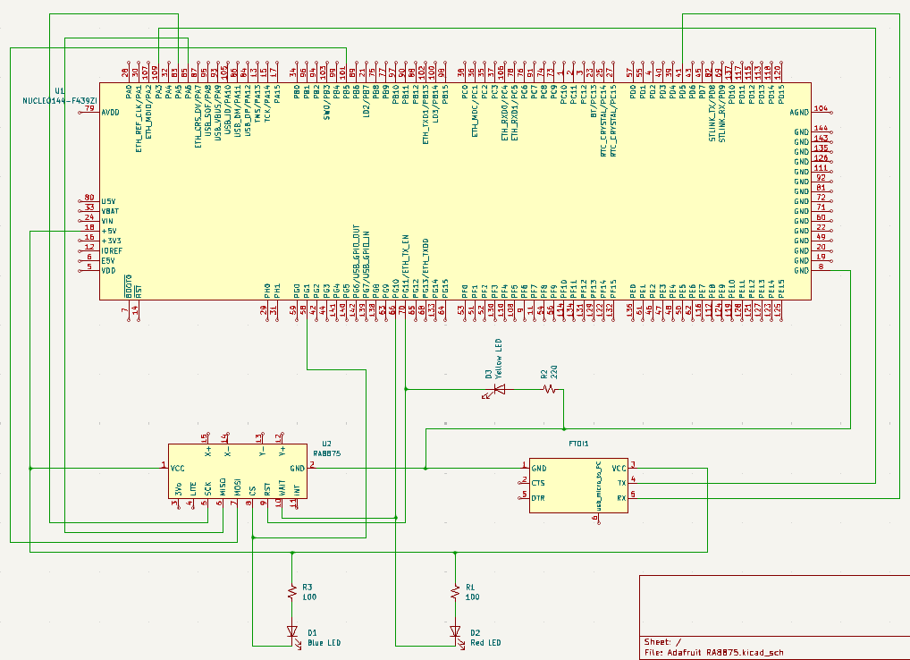
Schematic
The LED’s are for display purposes only. The Red LED indicates that the WAIT is low showing that the RA8875 CPU is busy. The Blue LED indicates that the CS (Chip Select) is low and that the Micro Processor is talking to the RA8875. When the Yellow LED goes off, this indicates that the RA8875 has been reset by the Micro Processor. If the Yellow LED is on, this indicates that the RA8875 is not in reset mode.
Pinouts & Configurations
Testing the Modifications
Before we get into examining the source code, let’s talk about how this code was translated from an Arduino Library into a library that can be used with the STM32 family of micro processors.
The Arduino Library was migrated into this project by reverse engineering the existing Arduino code and making appropriate changes to fit the architecture of the STM32 family. We then tested the code using two translated “Example INO Sketches”. The first being the Example “buildtest.ino” and the second was using Example “textmode.ino” both of these examples were also translated to fit into the STM32 Family design.
There were other cosmetic changes that were made to add text debug messages to display using the USART unto a dumb terminal with “printf()” statements. Other changes included adding delays to make the visual screen changes easier to see by slowing things down.
***Note: To clarify, we won’t actually be using the Arduino sketches, but are listed here for documentation purposes to show where our test code originated.
buildtest.ino
/******************************************************************
 This is an example for the Adafruit RA8875 Driver board for TFT displays
 ---------------> http://www.adafruit.com/products/1590
 The RA8875 is a TFT driver for up to 800x480 dotclock'd displays
 It is tested to work with displays in the Adafruit shop. Other displays
 may need timing adjustments and are not guanteed to work.

 Adafruit invests time and resources providing this open
 source code, please support Adafruit and open-source hardware
 by purchasing products from Adafruit!

 Written by Limor Fried/Ladyada for Adafruit Industries.
 BSD license, check license.txt for more information.
 All text above must be included in any redistribution.
 ******************************************************************/

#include <SPI.h>
#include "Adafruit_GFX.h"
#include "Adafruit_RA8875.h"


// Library only supports hardware SPI at this time
// Connect SCLK to UNO Digital #13 (Hardware SPI clock)
// Connect MISO to UNO Digital #12 (Hardware SPI MISO)
// Connect MOSI to UNO Digital #11 (Hardware SPI MOSI)
#define RA8875_INT 3
#define RA8875_CS 10
#define RA8875_RESET 9

Adafruit_RA8875 tft = Adafruit_RA8875(RA8875_CS, RA8875_RESET);
uint16_t tx, ty;

void setup()
{
  Serial.begin(9600);
  Serial.println("RA8875 start");

  /* Initialize the display using 'RA8875_480x80', 'RA8875_480x128', 'RA8875_480x272' or 'RA8875_800x480' */
  if (!tft.begin(RA8875_480x272)) {
    Serial.println("RA8875 Not Found!");
    while (1);
  }

  Serial.println("Found RA8875");

  tft.displayOn(true);
  tft.GPIOX(true);      // Enable TFT - display enable tied to GPIOX
  tft.PWM1config(true, RA8875_PWM_CLK_DIV1024); // PWM output for backlight
  tft.PWM1out(255);

  // With hardware accelleration this is instant
  tft.fillScreen(RA8875_WHITE);

  // Play with PWM
  for (uint8_t i=255; i!=0; i-=5 )
  {
    tft.PWM1out(i);
    delay(10);
  }
  for (uint8_t i=0; i!=255; i+=5 )
  {
    tft.PWM1out(i);
    delay(10);
  }
  tft.PWM1out(255);

  tft.fillScreen(RA8875_RED);
  delay(500);
  tft.fillScreen(RA8875_YELLOW);
  delay(500);
  tft.fillScreen(RA8875_GREEN);
  delay(500);
  tft.fillScreen(RA8875_CYAN);
  delay(500);
  tft.fillScreen(RA8875_MAGENTA);
  delay(500);
  tft.fillScreen(RA8875_BLACK);

  // Try some GFX acceleration!
  tft.drawCircle(100, 100, 50, RA8875_BLACK);
  tft.fillCircle(100, 100, 49, RA8875_GREEN);

  tft.fillRect(11, 11, 398, 198, RA8875_BLUE);
  tft.drawRect(10, 10, 400, 200, RA8875_GREEN);
  tft.fillRoundRect(200, 10, 200, 100, 10, RA8875_RED);
  tft.drawPixel(10,10,RA8875_BLACK);
  tft.drawPixel(11,11,RA8875_BLACK);
  tft.drawLine(10, 10, 200, 100, RA8875_RED);
  tft.drawTriangle(200, 15, 250, 100, 150, 125, RA8875_BLACK);
  tft.fillTriangle(200, 16, 249, 99, 151, 124, RA8875_YELLOW);
  tft.drawEllipse(300, 100, 100, 40, RA8875_BLACK);
  tft.fillEllipse(300, 100, 98, 38, RA8875_GREEN);
  // Argument 5 (curvePart) is a 2-bit value to control each corner (select 0, 1, 2, or 3)
  tft.drawCurve(50, 100, 80, 40, 2, RA8875_BLACK);
  tft.fillCurve(50, 100, 78, 38, 2, RA8875_WHITE);

  pinMode(RA8875_INT, INPUT);
  digitalWrite(RA8875_INT, HIGH);

  tft.touchEnable(true);

  Serial.print("Status: "); Serial.println(tft.readStatus(), HEX);
  Serial.println("Waiting for touch events ...");
}

void loop()
{
  float xScale = 1024.0F/tft.width();
  float yScale = 1024.0F/tft.height();

  /* Wait around for touch events */
  if (! digitalRead(RA8875_INT))
  {
    if (tft.touched())
    {
      Serial.print("Touch: ");
      tft.touchRead(&tx, &ty);
      Serial.print(tx); Serial.print(", "); Serial.println(ty);
      /* Draw a circle */
      tft.fillCircle((uint16_t)(tx/xScale), (uint16_t)(ty/yScale), 4, RA8875_WHITE);
    }
  }
}
textmode.ino
/******************************************************************
 This is an example for the Adafruit RA8875 Driver board for TFT displays
 ---------------> http://www.adafruit.com/products/1590
 The RA8875 is a TFT driver for up to 800x480 dotclock'd displays
 It is tested to work with displays in the Adafruit shop. Other displays
 may need timing adjustments and are not guanteed to work.

 Adafruit invests time and resources providing this open
 source code, please support Adafruit and open-source hardware
 by purchasing products from Adafruit!

 Written by Limor Fried/Ladyada for Adafruit Industries.
 BSD license, check license.txt for more information.
 All text above must be included in any redistribution.
 ******************************************************************/


#include <SPI.h>
#include "Adafruit_GFX.h"
#include "Adafruit_RA8875.h"

// Library only supports hardware SPI at this time
// Connect SCLK to UNO Digital #13 (Hardware SPI clock)
// Connect MISO to UNO Digital #12 (Hardware SPI MISO)
// Connect MOSI to UNO Digital #11 (Hardware SPI MOSI)
#define RA8875_INT 3
#define RA8875_CS 10
#define RA8875_RESET 9

Adafruit_RA8875 tft = Adafruit_RA8875(RA8875_CS, RA8875_RESET);
uint16_t tx, ty;

void setup()
{
  Serial.begin(9600);
  Serial.println("RA8875 start");

  /* Initialize the display using 'RA8875_480x80', 'RA8875_480x128', 'RA8875_480x272' or 'RA8875_800x480' */
  if (!tft.begin(RA8875_480x272)) {
    Serial.println("RA8875 Not Found!");
    while (1);
  }

  tft.displayOn(true);
  tft.GPIOX(true);      // Enable TFT - display enable tied to GPIOX
  tft.PWM1config(true, RA8875_PWM_CLK_DIV1024); // PWM output for backlight
  tft.PWM1out(255);
  tft.fillScreen(RA8875_BLACK);

  /* Switch to text mode */
  tft.textMode();
  tft.cursorBlink(32);


  /* Set a solid for + bg color ... */

  /* ... or a fore color plus a transparent background */


  /* Set the cursor location (in pixels) */
  tft.textSetCursor(10, 10);

  /* Render some text! */
  char string[15] = "Hello, World! ";
  tft.textTransparent(RA8875_WHITE);
  tft.textWrite(string);
  tft.textColor(RA8875_WHITE, RA8875_RED);
  tft.textWrite(string);
  tft.textTransparent(RA8875_CYAN);
  tft.textWrite(string);
  tft.textTransparent(RA8875_GREEN);
  tft.textWrite(string);
  tft.textColor(RA8875_YELLOW, RA8875_CYAN);
  tft.textWrite(string);
  tft.textColor(RA8875_BLACK, RA8875_MAGENTA);
  tft.textWrite(string);

  /* Change the cursor location and color ... */
  tft.textSetCursor(100, 100);
  tft.textTransparent(RA8875_RED);
  /* If necessary, enlarge the font */
  tft.textEnlarge(1);
  /* ... and render some more text! */
  tft.textWrite(string);
  tft.textSetCursor(100, 150);
  tft.textEnlarge(2);
  tft.textWrite(string);
}

void loop()
{
}
Exploring the Source Code
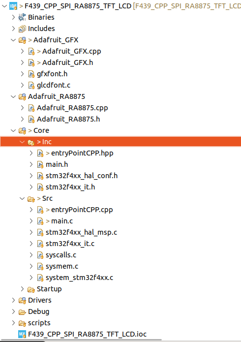
Project Structure
main.h
/* USER CODE BEGIN Header */
/**
  ******************************************************************************
  * @file           : main.h
  * @brief          : Header for main.c file.
  *                   This file contains the common defines of the application.
  ******************************************************************************
  * @attention
  *
  * Copyright (c) 2025 STMicroelectronics.
  * All rights reserved.
  *
  * This software is licensed under terms that can be found in the LICENSE file
  * in the root directory of this software component.
  * If no LICENSE file comes with this software, it is provided AS-IS.
  *
  ******************************************************************************
  */
/* USER CODE END Header */

/* Define to prevent recursive inclusion -------------------------------------*/
#ifndef __MAIN_H
#define __MAIN_H

#ifdef __cplusplus
extern "C" {
#endif

/* Includes ------------------------------------------------------------------*/
#include "stm32f4xx_hal.h"

/* Private includes ----------------------------------------------------------*/
/* USER CODE BEGIN Includes */

/* USER CODE END Includes */

/* Exported types ------------------------------------------------------------*/
/* USER CODE BEGIN ET */

/* USER CODE END ET */

/* Exported constants --------------------------------------------------------*/
/* USER CODE BEGIN EC */

/* USER CODE END EC */

/* Exported macro ------------------------------------------------------------*/
/* USER CODE BEGIN EM */

/* USER CODE END EM */

/* Exported functions prototypes ---------------------------------------------*/

/* USER CODE BEGIN EFP */

/* USER CODE END EFP */

/* Private defines -----------------------------------------------------------*/

/* USER CODE BEGIN Private defines */

void _Error_Handler(const char *, int);

#define Error_Handler() _Error_Handler((const char *)__FILE__, __LINE__)
#define REDIRECT_PRINTF

// Port and Pin #defines
#define RA8875_CS_Pin GPIO_PIN_1
#define RA8875_CS_GPIO_Port GPIOG
#define LCD_WAIT_Pin GPIO_PIN_10
#define LCD_WAIT_GPIO_Port GPIOG
#define LCD_RESET_Pin GPIO_PIN_11
#define LCD_RESET_GPIO_Port GPIOG

#define CS_DISABLE GPIO_PIN_SET
#define CS_ENABLE GPIO_PIN_RESET

/* USER CODE END Private defines */

#ifdef __cplusplus
}
#endif

#endif /* __MAIN_H */
main.c
We set the initial SPI baud rate low to make sure that we can communicate with the RA8875 chip and get a response on line 159. However, we change the SPI baud rate on line 173. The test functions are called on lines 183 and 185. These two calls essentially utilize the code taken from the two Arduino sketches mentioned previously.
/* USER CODE BEGIN Header */
/**
  ******************************************************************************
  * @file           : main.c
  * @brief          : Main program body
  ******************************************************************************
  * @attention
  *
  * Copyright (c) 2025 STMicroelectronics.
  * All rights reserved.
  *
  * This software is licensed under terms that can be found in the LICENSE file
  * in the root directory of this software component.
  * If no LICENSE file comes with this software, it is provided AS-IS.
  *
  ******************************************************************************
  */
/* USER CODE END Header */
/* Includes ------------------------------------------------------------------*/
#include "main.h"

/* Private includes ----------------------------------------------------------*/
/* USER CODE BEGIN Includes */
#include "stdio.h"
#include "string.h"
#include "stdbool.h"
#include "entryPointCPP.hpp"
/* USER CODE END Includes */

/* Private typedef -----------------------------------------------------------*/
/* USER CODE BEGIN PTD */

/* USER CODE END PTD */

/* Private define ------------------------------------------------------------*/
/* USER CODE BEGIN PD */

/* USER CODE END PD */

/* Private macro -------------------------------------------------------------*/
/* USER CODE BEGIN PM */

/* USER CODE END PM */

/* Private variables ---------------------------------------------------------*/
SPI_HandleTypeDef hspi1;

TIM_HandleTypeDef htim1;

UART_HandleTypeDef huart2;

/* USER CODE BEGIN PV */

/* USER CODE END PV */

/* Private function prototypes -----------------------------------------------*/
void SystemClock_Config(void);
static void MX_GPIO_Init(void);
static void MX_SPI1_Init(void);
static void MX_TIM1_Init(void);
static void MX_USART2_UART_Init(void);
/* USER CODE BEGIN PFP */

/* USER CODE END PFP */

/* Private user code ---------------------------------------------------------*/
/* USER CODE BEGIN 0 */

#ifdef REDIRECT_PRINTF
#define PUTCHAR_PROTOTYPE int __io_putchar(int ch)
#endif

#ifdef REDIRECT_PRINTF
/**
  * @brief  Retargets the C library printf function to the USART.
  * @param  None
  * @retval None
  */
PUTCHAR_PROTOTYPE
{
  /* Place your implementation of fputc here */
  /* e.g. write a character to the USART2 and Loop until the end of transmission */
  HAL_UART_Transmit(&huart2, (uint8_t *)&ch, 1, 0xFFFF);

  return ch;
}
#endif

void delay(uint16_t time)
{
	__HAL_TIM_SET_COUNTER(&htim1, 0);
	while (__HAL_TIM_GET_COUNTER (&htim1) < time);
}

void MX_SPI1_ReInit(uint32_t scaler)
{

  /* USER CODE BEGIN SPI1_Init 0 */

  /* USER CODE END SPI1_Init 0 */

  /* USER CODE BEGIN SPI1_Init 1 */

  /* USER CODE END SPI1_Init 1 */
  /* SPI1 parameter configuration*/
  hspi1.Instance = SPI1;
  hspi1.Init.Mode = SPI_MODE_MASTER;
  hspi1.Init.Direction = SPI_DIRECTION_2LINES;
  hspi1.Init.DataSize = SPI_DATASIZE_8BIT;
  hspi1.Init.CLKPolarity = SPI_POLARITY_LOW;
  hspi1.Init.CLKPhase = SPI_PHASE_1EDGE;
  hspi1.Init.NSS = SPI_NSS_SOFT;
  hspi1.Init.BaudRatePrescaler = scaler;
  hspi1.Init.FirstBit = SPI_FIRSTBIT_MSB;
  hspi1.Init.TIMode = SPI_TIMODE_DISABLE;
  hspi1.Init.CRCCalculation = SPI_CRCCALCULATION_DISABLE;
  hspi1.Init.CRCPolynomial = 10;
  if (HAL_SPI_Init(&hspi1) != HAL_OK)
  {
    Error_Handler();
  }
  /* USER CODE BEGIN SPI1_Init 2 */

  /* USER CODE END SPI1_Init 2 */

}

/* USER CODE END 0 */

/**
  * @brief  The application entry point.
  * @retval int
  */
int main(void)
{

  /* USER CODE BEGIN 1 */

  /* USER CODE END 1 */

  /* MCU Configuration--------------------------------------------------------*/

  /* Reset of all peripherals, Initializes the Flash interface and the Systick. */
  HAL_Init();

  /* USER CODE BEGIN Init */

  /* USER CODE END Init */

  /* Configure the system clock */
  SystemClock_Config();

  /* USER CODE BEGIN SysInit */

  /* USER CODE END SysInit */

  /* Initialize all configured peripherals */
  MX_GPIO_Init();
  MX_SPI1_Init();
  MX_TIM1_Init();
  MX_USART2_UART_Init();
  /* USER CODE BEGIN 2 */

  printf("\x1b[2J\x1b[H");	// Clear the dumb terminal screen
  printf("Starting Initialization Process\r\n");

  HAL_TIM_Base_Start(&htim1);

  initTest(&hspi1);

  HAL_Delay(1000);

  MX_SPI1_ReInit(SPI_BAUDRATEPRESCALER_32);	// Increase the SPI clock rate

  HAL_Delay(500);
  /* USER CODE END 2 */

  /* Infinite loop */
  /* USER CODE BEGIN WHILE */
  while (1)
  {
	  printf("Start Tests\r\n");
	  testLCD(true);
	  HAL_Delay(5000);
	  testLCD(false);
	  printf("Done\r\n");
	  HAL_Delay(5000);
    /* USER CODE END WHILE */

    /* USER CODE BEGIN 3 */
  }
  /* USER CODE END 3 */
}

/**
  * @brief System Clock Configuration
  * @retval None
  */
void SystemClock_Config(void)
{
  RCC_OscInitTypeDef RCC_OscInitStruct = {0};
  RCC_ClkInitTypeDef RCC_ClkInitStruct = {0};

  /** Configure the main internal regulator output voltage
  */
  __HAL_RCC_PWR_CLK_ENABLE();
  __HAL_PWR_VOLTAGESCALING_CONFIG(PWR_REGULATOR_VOLTAGE_SCALE1);

  /** Initializes the RCC Oscillators according to the specified parameters
  * in the RCC_OscInitTypeDef structure.
  */
  RCC_OscInitStruct.OscillatorType = RCC_OSCILLATORTYPE_HSI;
  RCC_OscInitStruct.HSIState = RCC_HSI_ON;
  RCC_OscInitStruct.HSICalibrationValue = RCC_HSICALIBRATION_DEFAULT;
  RCC_OscInitStruct.PLL.PLLState = RCC_PLL_ON;
  RCC_OscInitStruct.PLL.PLLSource = RCC_PLLSOURCE_HSI;
  RCC_OscInitStruct.PLL.PLLM = 8;
  RCC_OscInitStruct.PLL.PLLN = 180;
  RCC_OscInitStruct.PLL.PLLP = RCC_PLLP_DIV2;
  RCC_OscInitStruct.PLL.PLLQ = 4;
  if (HAL_RCC_OscConfig(&RCC_OscInitStruct) != HAL_OK)
  {
    Error_Handler();
  }

  /** Activate the Over-Drive mode
  */
  if (HAL_PWREx_EnableOverDrive() != HAL_OK)
  {
    Error_Handler();
  }

  /** Initializes the CPU, AHB and APB buses clocks
  */
  RCC_ClkInitStruct.ClockType = RCC_CLOCKTYPE_HCLK|RCC_CLOCKTYPE_SYSCLK
                              |RCC_CLOCKTYPE_PCLK1|RCC_CLOCKTYPE_PCLK2;
  RCC_ClkInitStruct.SYSCLKSource = RCC_SYSCLKSOURCE_PLLCLK;
  RCC_ClkInitStruct.AHBCLKDivider = RCC_SYSCLK_DIV1;
  RCC_ClkInitStruct.APB1CLKDivider = RCC_HCLK_DIV4;
  RCC_ClkInitStruct.APB2CLKDivider = RCC_HCLK_DIV2;

  if (HAL_RCC_ClockConfig(&RCC_ClkInitStruct, FLASH_LATENCY_5) != HAL_OK)
  {
    Error_Handler();
  }
}

/**
  * @brief SPI1 Initialization Function
  * @param None
  * @retval None
  */
static void MX_SPI1_Init(void)
{

  /* USER CODE BEGIN SPI1_Init 0 */

  /* USER CODE END SPI1_Init 0 */

  /* USER CODE BEGIN SPI1_Init 1 */

  /* USER CODE END SPI1_Init 1 */
  /* SPI1 parameter configuration*/
  hspi1.Instance = SPI1;
  hspi1.Init.Mode = SPI_MODE_MASTER;
  hspi1.Init.Direction = SPI_DIRECTION_2LINES;
  hspi1.Init.DataSize = SPI_DATASIZE_8BIT;
  hspi1.Init.CLKPolarity = SPI_POLARITY_LOW;
  hspi1.Init.CLKPhase = SPI_PHASE_1EDGE;
  hspi1.Init.NSS = SPI_NSS_SOFT;
  hspi1.Init.BaudRatePrescaler = SPI_BAUDRATEPRESCALER_128;
  hspi1.Init.FirstBit = SPI_FIRSTBIT_MSB;
  hspi1.Init.TIMode = SPI_TIMODE_DISABLE;
  hspi1.Init.CRCCalculation = SPI_CRCCALCULATION_DISABLE;
  hspi1.Init.CRCPolynomial = 10;
  if (HAL_SPI_Init(&hspi1) != HAL_OK)
  {
    Error_Handler();
  }
  /* USER CODE BEGIN SPI1_Init 2 */

  /* USER CODE END SPI1_Init 2 */

}

/**
  * @brief TIM1 Initialization Function
  * @param None
  * @retval None
  */
static void MX_TIM1_Init(void)
{

  /* USER CODE BEGIN TIM1_Init 0 */

  /* USER CODE END TIM1_Init 0 */

  TIM_ClockConfigTypeDef sClockSourceConfig = {0};
  TIM_MasterConfigTypeDef sMasterConfig = {0};

  /* USER CODE BEGIN TIM1_Init 1 */

  /* USER CODE END TIM1_Init 1 */
  htim1.Instance = TIM1;
  htim1.Init.Prescaler = 180-1;
  htim1.Init.CounterMode = TIM_COUNTERMODE_UP;
  htim1.Init.Period = 65535;
  htim1.Init.ClockDivision = TIM_CLOCKDIVISION_DIV1;
  htim1.Init.RepetitionCounter = 0;
  htim1.Init.AutoReloadPreload = TIM_AUTORELOAD_PRELOAD_DISABLE;
  if (HAL_TIM_Base_Init(&htim1) != HAL_OK)
  {
    Error_Handler();
  }
  sClockSourceConfig.ClockSource = TIM_CLOCKSOURCE_INTERNAL;
  if (HAL_TIM_ConfigClockSource(&htim1, &sClockSourceConfig) != HAL_OK)
  {
    Error_Handler();
  }
  sMasterConfig.MasterOutputTrigger = TIM_TRGO_RESET;
  sMasterConfig.MasterSlaveMode = TIM_MASTERSLAVEMODE_DISABLE;
  if (HAL_TIMEx_MasterConfigSynchronization(&htim1, &sMasterConfig) != HAL_OK)
  {
    Error_Handler();
  }
  /* USER CODE BEGIN TIM1_Init 2 */

  /* USER CODE END TIM1_Init 2 */

}

/**
  * @brief USART2 Initialization Function
  * @param None
  * @retval None
  */
static void MX_USART2_UART_Init(void)
{

  /* USER CODE BEGIN USART2_Init 0 */

  /* USER CODE END USART2_Init 0 */

  /* USER CODE BEGIN USART2_Init 1 */

  /* USER CODE END USART2_Init 1 */
  huart2.Instance = USART2;
  huart2.Init.BaudRate = 19200;
  huart2.Init.WordLength = UART_WORDLENGTH_8B;
  huart2.Init.StopBits = UART_STOPBITS_1;
  huart2.Init.Parity = UART_PARITY_NONE;
  huart2.Init.Mode = UART_MODE_TX_RX;
  huart2.Init.HwFlowCtl = UART_HWCONTROL_NONE;
  huart2.Init.OverSampling = UART_OVERSAMPLING_16;
  if (HAL_UART_Init(&huart2) != HAL_OK)
  {
    Error_Handler();
  }
  /* USER CODE BEGIN USART2_Init 2 */

  /* USER CODE END USART2_Init 2 */

}

/**
  * @brief GPIO Initialization Function
  * @param None
  * @retval None
  */
static void MX_GPIO_Init(void)
{
  GPIO_InitTypeDef GPIO_InitStruct = {0};
/* USER CODE BEGIN MX_GPIO_Init_1 */
/* USER CODE END MX_GPIO_Init_1 */

  /* GPIO Ports Clock Enable */
  __HAL_RCC_GPIOC_CLK_ENABLE();
  __HAL_RCC_GPIOH_CLK_ENABLE();
  __HAL_RCC_GPIOA_CLK_ENABLE();
  __HAL_RCC_GPIOG_CLK_ENABLE();
  __HAL_RCC_GPIOD_CLK_ENABLE();
  __HAL_RCC_GPIOB_CLK_ENABLE();

  /*Configure GPIO pin Output Level */
  HAL_GPIO_WritePin(GPIOG, GPIO_PIN_1|GPIO_PIN_10|GPIO_PIN_11, GPIO_PIN_RESET);

  /*Configure GPIO pin : PG1 */
  GPIO_InitStruct.Pin = GPIO_PIN_1;
  GPIO_InitStruct.Mode = GPIO_MODE_OUTPUT_PP;
  GPIO_InitStruct.Pull = GPIO_PULLUP;
  GPIO_InitStruct.Speed = GPIO_SPEED_FREQ_LOW;
  HAL_GPIO_Init(GPIOG, &GPIO_InitStruct);

  /*Configure GPIO pins : PG10 PG11 */
  GPIO_InitStruct.Pin = GPIO_PIN_10|GPIO_PIN_11;
  GPIO_InitStruct.Mode = GPIO_MODE_OUTPUT_PP;
  GPIO_InitStruct.Pull = GPIO_NOPULL;
  GPIO_InitStruct.Speed = GPIO_SPEED_FREQ_LOW;
  HAL_GPIO_Init(GPIOG, &GPIO_InitStruct);

/* USER CODE BEGIN MX_GPIO_Init_2 */
/* USER CODE END MX_GPIO_Init_2 */
}

/* USER CODE BEGIN 4 */


/**
 * @brief  This function is executed in case of error occurrence.
 * @param  file: The file name as string.
 * @param  line: The line in file as a number.
 * @retval None
 */
void _Error_Handler(const char *file, int line)
{
	/* USER CODE BEGIN Error_Handler_Debug */
	  __disable_irq();
#ifdef REDIRECT_PRINTF
	char buf[80];
	sprintf(buf, "Trapped in Error_Handler().  Called from: %s, line: %d\r\n", file, line);
	printf(buf);
#endif
	/* User can add his own implementation to report the HAL error return state */
	while(1)
	{
	}
}

/* USER CODE END 4 */

#ifdef  USE_FULL_ASSERT
/**
  * @brief  Reports the name of the source file and the source line number
  *         where the assert_param error has occurred.
  * @param  file: pointer to the source file name
  * @param  line: assert_param error line source number
  * @retval None
  */
void assert_failed(uint8_t *file, uint32_t line)
{
  /* USER CODE BEGIN 6 */
  /* User can add his own implementation to report the file name and line number,
     ex: printf("Wrong parameters value: file %s on line %d\r\n", file, line) */
  /* USER CODE END 6 */
}
#endif /* USE_FULL_ASSERT */
entryPointCPP.hpp
/*
 * entryPointCPP.hpp
 *
 *  Created on: Jan 26, 2025
 *      Author: johng
 */

#ifndef INC_ENTRYPOINTCPP_HPP_
#define INC_ENTRYPOINTCPP_HPP_


#include "main.h"

// Define all C function calls that will be called from main.c in the following extern "C" group
// Using extern "C" stops name mangling and allows "C" code to call C++ code

#ifdef __cplusplus
extern "C" {
#endif
	void initTest(SPI_HandleTypeDef *halSPI);
	void testLCD(bool buildTest);
#ifdef __cplusplus
}
#endif


#endif /* INC_ENTRYPOINTCPP_HPP_ */
entryPointCPP.cpp
This C++ source file is the how we are able to call C++ code from main.c It is the gateway to the C++ world in our code. This allows us to create C++ objects and call member functions in the instantiated objects. Line 25 is where we are creating the C++ object Adafruit_RA8875. Keep in mind that class Adafruit_RA8875 is a derived class off of class Adafruit_GFX, which is why you see this “class Adafruit_RA8875 : public Adafruit_GFX” in the declaration of class Adafruit_RA8875 in the include file Adafruit_RA8875.h on line 118. Even though the tests do not use the Adafruit_GFX library, we had to also convert it to compile with STM32 Micro Processors, because of the inheritance.
/*
 * entryPointCPP.cpp
 *
 *  Created on: Jan 26, 2025
 *      Author: johng
 */

#include "entryPointCPP.hpp"
#include "Adafruit_RA8875.h"


Adafruit_RA8875 *tft;

void initTest(SPI_HandleTypeDef *halSPI) {
	HAL_GPIO_WritePin(RA8875_CS_GPIO_Port, RA8875_CS_Pin, CS_DISABLE);

	HAL_GPIO_WritePin(LCD_RESET_GPIO_Port, LCD_RESET_Pin, GPIO_PIN_SET);
	delay(100);
	HAL_GPIO_WritePin(LCD_RESET_GPIO_Port, LCD_RESET_Pin, GPIO_PIN_RESET);
	delay(100);
	HAL_GPIO_WritePin(LCD_RESET_GPIO_Port, LCD_RESET_Pin, GPIO_PIN_SET);

	HAL_GPIO_WritePin(LCD_WAIT_GPIO_Port, LCD_WAIT_Pin, GPIO_PIN_SET);

	tft = new Adafruit_RA8875(halSPI);

	int stat = tft->begin(RA8875_800x480);

	if (stat) {
	  printf("RA8875 Found\r\n");
	} else {
	  Error_Handler();
	  }
}

void testLCD(bool buildTest) {
	if (buildTest) {
		printf("================  Graphics Mode =============\r\n");

	  tft->displayOn(true);
	  HAL_Delay(1);
	  tft->GPIOX(true);
	  HAL_Delay(1);
	  tft->PWM1config(true, RA8875_PWM_CLK_DIV1024);
	  tft->PWM1out(255);
	  HAL_Delay(1);

	  tft->graphicsMode();

	  tft->fillScreen(RA8875_WHITE);
	  HAL_Delay(1000);
	  // Play with PWM
	  printf("Start: Play with PWM\r\n");

	  for (uint8_t i=255; i!=0; i-=5 )
	  {
		tft->PWM1out(i);
		delay(100);
	  }
	  for (uint8_t i=0; i!=255; i+=5 )
	  {
		tft->PWM1out(i);
		delay(100);
	  }
	  tft->PWM1out(255);

	  printf("END: Play with PWM\r\n");
	  HAL_Delay(2000);

	  printf("FillSreen Red\r\n");
	  tft->fillScreen(RA8875_RED);
	  HAL_Delay(1000);
	  printf("FillSreen Yellow\r\n");
	  tft->fillScreen(RA8875_YELLOW);
	  HAL_Delay(1000);
	  printf("FillSreen Green\r\n");
	  tft->fillScreen(RA8875_GREEN);
	  HAL_Delay(1000);
	  printf("FillSreen Cyan\r\n");
	  tft->fillScreen(RA8875_CYAN);
	  HAL_Delay(1000);
	  printf("FillSreen Magenta\r\n");
	  tft->fillScreen(RA8875_MAGENTA);
	  HAL_Delay(1000);
	  printf("FillSreen Black\r\n");
	  tft->fillScreen(RA8875_BLACK);
	  HAL_Delay(1000);

	  // Try some GFX acceleration!
	  printf("drawCircle\r\n");
	  tft->drawCircle(100, 100, 50, RA8875_BLACK);
	  printf("fillCircle\r\n");
	  tft->fillCircle(100, 100, 49, RA8875_GREEN);

	  HAL_Delay(1000);

	  printf("fillRect\r\n");
	  tft->fillRect(11, 11, 398, 198, RA8875_BLUE);
	  HAL_Delay(1000);
	  printf("drawRect\r\n");
	  tft->drawRect(10, 10, 400, 200, RA8875_GREEN);
	  HAL_Delay(1000);
	  printf("fillRoundRect\r\n");
	  tft->fillRoundRect(200, 10, 200, 100, 10, RA8875_RED);
	  HAL_Delay(1000);
	  printf("drawPixel\r\n");
	  tft->drawPixel(10,10,RA8875_BLACK);
	  HAL_Delay(1000);
	  printf("drawPixel\r\n");
	  tft->drawPixel(11,11,RA8875_BLACK);
	  HAL_Delay(1000);
	  printf("drawLine\r\n");
	  tft->drawLine(10, 10, 200, 100, RA8875_RED);
	  HAL_Delay(1000);
	  printf("drawTriangle\r\n");
	  tft->drawTriangle(200, 15, 250, 100, 150, 125, RA8875_BLACK);
	  HAL_Delay(1000);
	  printf("fillTriangle\r\n");
	  tft->fillTriangle(200, 16, 249, 99, 151, 124, RA8875_YELLOW);
	  HAL_Delay(1000);
	  printf("drawEllipse\r\n");
	  tft->drawEllipse(300, 100, 100, 40, RA8875_BLACK);
	  HAL_Delay(1000);
	  printf("fillEllipse\r\n");
	  tft->fillEllipse(300, 100, 98, 38, RA8875_GREEN);
	  HAL_Delay(1000);
	  // Argument 5 (curvePart) is a 2-bit value to control each corner (select 0, 1, 2, or 3)
	  printf("drawCurve\r\n");
	  tft->drawCurve(50, 100, 80, 40, 2, RA8875_BLACK);
	  HAL_Delay(1000);
	  printf("fillCurve\r\n");
	  tft->fillCurve(50, 100, 78, 38, 2, RA8875_WHITE);
	} else {
		printf("================  Text Mode =============\r\n");
	  tft->displayOn(true);
	  tft->GPIOX(true);      // Enable TFT - display enable tied to GPIOX
	  tft->PWM1config(true, RA8875_PWM_CLK_DIV1024); // PWM output for backlight
	  tft->PWM1out(255);
	  printf("fillScreen\r\n");
	  tft->fillScreen(RA8875_BLACK);

	  /* Switch to text mode */
	  tft->textMode();
	  tft->cursorBlink(32);


	  /* Set a solid for + bg color ... */

	  /* ... or a fore color plus a transparent background */


	  /* Set the cursor location (in pixels) */
	  tft->textSetCursor(10, 10);

	  /* Render some text! */
	  printf("Render lots of Texts\r\n");
	  char string[80] = "Hello, World! ";
	  tft->textTransparent(RA8875_WHITE);
	  tft->textWrite(string);
	  HAL_Delay(500);
	  tft->textColor(RA8875_WHITE, RA8875_RED);
	  tft->textWrite(string);
	  HAL_Delay(500);
	  tft->textTransparent(RA8875_CYAN);
	  tft->textWrite(string);
	  HAL_Delay(500);
	  tft->textTransparent(RA8875_GREEN);
	  tft->textWrite(string);
	  HAL_Delay(500);
	  tft->textColor(RA8875_YELLOW, RA8875_CYAN);
	  tft->textWrite(string);
	  HAL_Delay(500);
	  tft->textColor(RA8875_BLACK, RA8875_MAGENTA);
	  tft->textWrite(string);

	  HAL_Delay(1000);

	  tft->textSetCursor(100, 100);
	  tft->textEnlarge(1);
	  tft->textTransparent(RA8875_YELLOW);
	  tft->textWrite(string);

	  tft->textSetCursor(100, 150);
	  tft->textEnlarge(2);
	  tft->textTransparent(RA8875_YELLOW);
	  tft->textWrite(string);

	  tft->textSetCursor(100, 200);
	  tft->textEnlarge(3);
	  tft->textTransparent(RA8875_YELLOW);
	  tft->textWrite(string);

	  tft->textSetCursor(100, 300);
	  tft->textEnlarge(0);
	  tft->textTransparent(RA8875_YELLOW);
	  tft->textWrite(string);
	}
}
Download the Device Driver Library
Demo Video
The original Arduino Example code converted for this demo, executed much faster, but there were delays added to the code to allow the viewer to see each step that was being executed. Otherwise this demo would have finished in less than 15 seconds.
If you have questions or run into trouble getting the boards programmed and talking to each other, post in the Tutorial Support forum and I will work through it with you. If project source is not linked in the tutorial, it may be available on request — use the email contact option in the site footer.