Overview
In the first part of this series, STM32 SX1262 Encrypted LoRa (Part 1) Secures with AES, we built an STM32 SX1262 encrypted LoRa link and gave it confidentiality: payloads were encrypted with AES so a passive listener could not read them. Confidentiality, though, is only one of the four properties a secure link needs. An attacker who cannot read your traffic can still tamper with it, forge frames, or replay a captured frame later. Part 2 closes those gaps.
This tutorial walks through the RadioLink protocol layer (radioLink/) and the FRAM persistence driver (ADA1897_MB85RS64B/) of the project. You will see how AES-CTR provides streaming encryption sized for LoRa frames, how AES-CMAC adds authentication without introducing a second cryptographic primitive, why replay protection is still required after a frame authenticates, and how a monotonic counter stored in FRAM keeps that replay protection intact across power cycles. The end result is the Wire v3 frame format: an authenticated, replay-resistant encrypted packet.
As with Part 1, the full project source and Doxygen documentation are available for download at the end of the tutorial. No code changes are required to follow along — this installment explains code that already ships in the project package.
- Overview
- What You Will Learn
- Prerequisites
- Materials List
- Project Structure
- Hardware Configuration / Pinouts
- Project Setup
- Code Walkthrough
- From Confidentiality to Authenticated Encryption
- AES-CTR: Streaming Encryption for LoRa Frames
- Why Not Just Use AES-GCM?
- AES-CMAC: Authentication Without Re-Inventing the Primitive
- Replay Protection: The Counter That Makes Authentication Complete
- FRAM Persistence: Why the Counter Must Survive Power Cycles
- FRAM Driver Walkthrough (MB85RS64B over SPI)
- Wire v3 Frame Format
- Code Walkthrough — TX Pipeline
- Code Walkthrough — RX Pipeline
- Project Downloads
- Documentation
What You Will Learn
- Why AES-CTR is a better fit than AES-CBC for short, streaming LoRa frames
- How the CTR nonce is derived from the session ID and message counter
- Why confidentiality alone does not stop tampering or forgery
- How AES-CMAC authenticates a frame by reusing the AES block cipher you already have
- Why the project uses CTR + CMAC instead of AES-GCM
- Why an authenticated frame can still be replayed, and how a monotonic counter prevents it
- How the MB85RS64B SPI FRAM stores the counter so replay protection survives a reboot
- How the Wire v3 frame format ties encryption, authentication, and replay state together
Prerequisites
This tutorial assumes you have completed Part 1 of this series, which covers the hardware wiring, the SX1262 driver, and the basic AES setup on the STM32F439. You should be comfortable with:
- STM32CubeIDE and the STM32 HAL
- Basic SPI peripheral usage on STM32
- The SX1262 LoRa driver and frame transmit/receive flow from Part 1
- C structs, pointers, and bitwise operations
A working knowledge of AES at the “block cipher that takes a key and a 16-byte block” level is enough. The cryptographic concepts — counter mode, CMAC, replay windows — are explained from first principles as they come up.
Materials List
- STM32 Nucleo-F439ZI development board (2× — one TX, one RX)
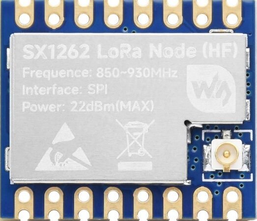
- SX1262 LoRa module (2×)
- Adafruit MB85RS64B SPI FRAM breakout (ADA1897) — on the TX node
- Jumper wires and breadboard
- Two USB cables for power and ST-LINK debugging
- STM32CubeIDE (for building and flashing the project)
Only the TX node strictly needs the FRAM module: the transmitter is the side that must persist its counter. The receiver keeps its replay state in RAM, as explained in the replay-protection section below.
Project Structure
The project layout is unchanged from Part 1. The two directories most relevant to this tutorial are marked below: radioLink/ holds the Wire v3 protocol layer (framing, AES-CTR, AES-CMAC, replay checks), and ADA1897_MB85RS64B/ holds the SPI FRAM driver used for counter persistence. The qaTests/ directory is the subject of Part 3 and can be ignored for now.
F439_CPP_TX-RX_LoRa_Project_01/
├── ADA1897_MB85RS64B/         <-- SPI FRAM driver (persistence layer)
│   ├── ada1897_mb85rs64b.c
│   └── ada1897_mb85rs64b.h
├── Core/                      <-- CubeMX-generated HAL + main.c
│   ├── Inc/
│   │   ├── main.h
│   │   ├── stm32f4xx_hal_conf.h
│   │   └── stm32f4xx_it.h
│   ├── Src/
│   │   ├── main.c
│   │   ├── stm32f4xx_hal_msp.c
│   │   ├── stm32f4xx_it.c
│   │   ├── syscalls.c
│   │   ├── sysmem.c
│   │   └── system_stm32f4xx.c
│   ├── Startup/
│   └── ThreadSafe/
├── Drivers/                   <-- ST HAL + CMSIS (CubeMX-managed)
├── SX1262/                    <-- SX1262 LoRa radio driver
│   ├── sx1262.c
│   └── sx1262.h
├── radioApp/                  <-- Application layer
│   ├── radio_app.c
│   └── radio_app.h
├── radioLink/                 <-- Protocol layer (Wire v3, crypto, replay)
│   ├── radio_link.c
│   ├── radio_link.h
│   └── radio_wire.h
├── qaTests/                   <-- Hostile-frame QA harness (covered in Part 3)
│   ├── protocol/
│   └── qaApp/
├── docs/                      <-- Doxygen output
├── scripts/                   <-- Build / instrumentation helpers
├── F439_CPP_TX-RX_LoRa_Project_01.ioc
├── STM32F439ZITX_FLASH.ld
├── Doxyfile
└── README.mdHardware Configuration / Pinouts
Overview
The wiring from Part 1 carries over unchanged: the SX1262 radio is on the SPI bus with its control lines (CS, BUSY, NRESET, DIO1) mapped to GPIO, and the on-chip AES engine (CRYP peripheral) needs no external wiring. Part 2 adds one peripheral: the MB85RS64B FRAM, which sits on SPI1 with a dedicated chip-select line.
Two peripheral configurations matter for this tutorial. The first is the CRYP peripheral, configured for AES in counter mode. These values are read directly from Core/Src/main.c rather than the CubeMX .ioc export, because the source file is the authoritative record of what the firmware actually initializes:
static void MX_CRYP_Init(void)
{
  hcryp.Instance = CRYP;
  hcryp.Init.DataType = CRYP_DATATYPE_32B;
  hcryp.Init.KeySize = CRYP_KEYSIZE_128B;
  hcryp.Init.pKey = (uint32_t *)pKeyCRYP;
  hcryp.Init.pInitVect = (uint32_t *)pInitVectCRYP;
  hcryp.Init.Algorithm = CRYP_AES_CTR;
  hcryp.Init.DataWidthUnit = CRYP_DATAWIDTHUNIT_BYTE;
  if (HAL_CRYP_Init(&hcryp) != HAL_OK)
  {
    Error_Handler();
  }
}The key fields: Algorithm = CRYP_AES_CTR selects counter mode, KeySize = CRYP_KEYSIZE_128B selects AES-128, and DataWidthUnit = CRYP_DATAWIDTHUNIT_BYTE lets the driver accept payload lengths that are not multiples of 16 — which matters for CTR mode, as the encryption section explains. The pKey and pInitVect fields point at placeholder buffers here; RadioLink overrides them per frame with the real key and nonce.
The second is SPI1, which drives the FRAM. The relevant settings are 8-bit data size, mode 0 (CLKPolarity low, CLKPhase 1-edge), software-managed chip select, and a prescaler of 64:
static void MX_SPI1_Init(void)
{
  hspi1.Instance = SPI1;
  hspi1.Init.Mode = SPI_MODE_MASTER;
  hspi1.Init.Direction = SPI_DIRECTION_2LINES;
  hspi1.Init.DataSize = SPI_DATASIZE_8BIT;
  hspi1.Init.CLKPolarity = SPI_POLARITY_LOW;
  hspi1.Init.CLKPhase = SPI_PHASE_1EDGE;
  hspi1.Init.NSS = SPI_NSS_SOFT;
  hspi1.Init.BaudRatePrescaler = SPI_BAUDRATEPRESCALER_64;
  hspi1.Init.FirstBit = SPI_FIRSTBIT_MSB;
  hspi1.Init.TIMode = SPI_TIMODE_DISABLE;
  hspi1.Init.CRCCalculation = SPI_CRCCALCULATION_DISABLE;
  hspi1.Init.CRCPolynomial = 10;
  if (HAL_SPI_Init(&hspi1) != HAL_OK)
  {
    Error_Handler();
  }
}Pinouts & Configurations
The full pin assignment and clock configuration for the project is exported from STM32CubeMX. Download the PDF below for the complete reference.
Project Setup
If you followed Part 1, the project is already set up — Part 2 adds no new CubeMX peripherals beyond the SPI1/FRAM wiring noted above, and the RadioLink and FRAM code already ships in the downloadable package. To follow along:
- Download and extract the project package linked at the end of this tutorial.
- Open the project in STM32CubeIDE.
- Build it once to confirm your toolchain is set up (no code changes are needed).
- Open
radioLink/radio_link.c,radioLink/radio_wire.h, andADA1897_MB85RS64B/ada1897_mb85rs64b.calongside this tutorial — the walkthrough refers to them throughout.
One build switch is worth knowing about up front. In radio_link.h, persistence is governed by two macros:
/* Persistence policy */
#define RL_PERSIST_ENABLE                 1
#define RL_PERSIST_DISABLE_WHEN_DEBUGGER 1RL_PERSIST_ENABLE turns FRAM persistence on or off globally. RL_PERSIST_DISABLE_WHEN_DEBUGGER additionally suppresses persistence whenever a debugger is attached — this prevents your debug sessions from burning counter values into FRAM while you single-step. Both are explained in the FRAM section.
Code Walkthrough
The walkthrough follows the same cause-and-effect path the protocol itself takes. We start with encryption (AES-CTR), see why encryption alone is not enough and reach for authentication (AES-CMAC), see why authentication alone still allows replay and add a monotonic counter, and finally see why that counter must live in FRAM. The Wire v3 frame format then ties all three together, and the TX and RX pipelines show the composed result.
From Confidentiality to Authenticated Encryption
Part 1 left the link with one property: a passive eavesdropper cannot read the payload. Consider what an active attacker can still do against an encrypted-but-unauthenticated link:
- Tamper. Flip bits in the ciphertext. In a stream cipher construction like CTR, flipping one ciphertext bit flips exactly the corresponding plaintext bit — the attacker does not need the key to make a controlled change to the decrypted message.
- Forge. Transmit an arbitrary frame. The receiver will decrypt whatever arrives; without authentication it has no way to tell a genuine frame from random bytes dressed up as one.
- Replay. Capture a valid frame off the air and retransmit it later. It was valid once, so it decrypts cleanly again.
Closing these requires three more properties on top of confidentiality: integrity (the frame was not modified), authenticity (the frame came from a holder of the shared key), and replay protection (the frame is fresh, not a recording). The RadioLink security model states this threat model explicitly — the attacker may inject, replay, and probe the parser, but does not hold the shared key. The runtime crypto context reflects the split this leads to:
// === RADIOLINK_CRYPTO_CONTEXT ===
/**
 * @brief Runtime crypto context for RadioLink key material.
 */
typedef struct radioLinkCryptoCtx_t {
    uint8_t masterKey[16];
    uint8_t encKey[16];
    uint8_t macKey[16];
    uint8_t keyIsValid;   // 0/1
} radioLinkCryptoCtx_t;There is a masterKey, and two working keys derived from it: encKey for AES-CTR encryption and macKey for AES-CMAC authentication. Using separate keys for encryption and authentication is a deliberate design rule — it keeps the two operations cryptographically independent. The key-derivation function that fills these fields is, in the current project state, a documented placeholder:
static void radioLinkDeriveKeys(radioLinkCryptoCtx_t *ctx, uint8_t nodeId)
{
    (void)nodeId;

    if (ctx == NULL) {
        return;
    }

    // Placeholder: copy masterKey into encKey/macKey so we have deterministic bytes.
    // Real implementation will derive separate keys (ENC/MAC labels) using CMAC.
    for (uint32_t i = 0u; i < 16u; i++) {
        ctx->encKey[i] = ctx->masterKey[i];
        ctx->macKey[i] = ctx->masterKey[i];
    }

    ctx->keyIsValid = 1u;
}As the comment states, the working keys are presently copied verbatim from the master key; the intended implementation derives distinct ENC and MAC keys using CMAC as a key-derivation function. The radioLinkCryptoCtx_t structure is already shaped for the final design, so the rest of the protocol code — which always reads encKey and macKey, never masterKey directly — will not change when the derivation is completed. This is worth being honest about: the structure enforces key separation, and the derivation step is the remaining piece.
AES-CTR: Streaming Encryption for LoRa Frames
AES is a block cipher: it transforms one fixed 16-byte block at a time. A mode of operation is what turns that single-block primitive into something that can encrypt a message of any length. Part 1 introduced AES; Part 2 is specific about the mode, and the choice is CTR (counter) mode.
The reason comes down to the shape of LoRa traffic. A Wire v3 frame carries at most 228 bytes of payload, and that payload is rarely a multiple of 16. Compare the two candidate modes against that constraint:
- AES-CBC encrypts 16-byte blocks in a chain. A message that is not a multiple of 16 bytes must be padded up to a block boundary, so a 43-byte payload becomes 48 bytes on the air. On a link where every byte costs airtime, that is wasted budget. CBC also cannot decrypt a block until the previous one arrives intact.
- AES-CTR turns AES into a keystream generator. It encrypts a counter block to produce 16 bytes of keystream, and XORs that keystream with the plaintext. The ciphertext is therefore exactly as long as the plaintext — no padding, no block alignment. A 43-byte payload encrypts to 43 bytes.
That length transparency is why the CRYP peripheral is configured with DataWidthUnit = CRYP_DATAWIDTHUNIT_BYTE: the hardware will process a byte count that is not a multiple of the block size. Here is the entire CTR helper in RadioLink:
static bool radioLinkAesCtrXor(uint8_t *data,
                               uint32_t len,
                               const uint8_t key[16],
                               const uint8_t nonce[16])
{
    HAL_StatusTypeDef status;

    if ((data == NULL) || (key == NULL) || (nonce == NULL) || (len == 0u)) {
        return false;
    }

    /* CRYP driver expects key/IV pointers via init struct (CubeMX style) */
    hcryp.Init.pKey = (uint32_t *)key;
    hcryp.Init.pInitVect = (uint32_t *)nonce;

    status = HAL_CRYP_Init(&hcryp);
    if (status != HAL_OK) {
        return false;
    }

    /*
     * AES-CTR is symmetric: "encrypt" produces keystream XOR.
     * Use Encrypt for both encrypt/decrypt.
     */
    status = HAL_CRYP_Encrypt(&hcryp,
                              (uint32_t *)data,
                              len,
                              (uint32_t *)data,
                              HAL_MAX_DELAY);

    if (status != HAL_OK) {
        return false;
    }

    return true;
}Two things are worth highlighting. First, the same function is used for both encryption and decryption — CTR mode is symmetric, because XORing the keystream a second time recovers the original bytes. The comment in the code says exactly this. Second, the security of CTR mode rests entirely on one rule: a (key, nonce) pair must never be reused. If two messages are ever encrypted with the same key and the same nonce, they share a keystream, and XORing the two ciphertexts cancels the keystream and leaks the relationship between the plaintexts.
RadioLink satisfies that rule by constructing the 16-byte nonce from two values that, together, never repeat:
    memset(nonce, 0, sizeof(nonce));
    RadioLink_EncodeLe32(&nonce[0], sessionSeqId);
RadioLink_EncodeLe32(&nonce[4], msgCounter);The low 4 bytes are the sessionSeqId — a value that advances once per boot — and the next 4 bytes are the msgCounter, which advances once per transmitted frame. The session ID changes every power cycle; the counter changes every frame within a session. The pair is unique for the life of the device. And notice that these are the same two fields used for replay protection later — nonce uniqueness and replay defense are driven by a single source of truth, which is a large part of why the design hangs together cleanly.
Why Not Just Use AES-GCM?
A reader familiar with modern cryptography will ask the obvious question at this point: AES-GCM is a standard authenticated-encryption mode that provides confidentiality and authentication in a single construction. Why build CTR + CMAC by hand instead of using GCM?
It is a fair question, and GCM is an excellent mode. The project’s choice is a set of engineering trade-offs rather than a claim that GCM is wrong:
- One primitive to audit. CTR mode is AES in a loop. CMAC is also AES in a loop. The entire cryptographic surface of RadioLink is the AES block cipher — nothing else. GCM additionally requires GHASH, a carry-less Galois-field multiplication that is a separate primitive to implement, test, and trust. On a small embedded codebase you maintain yourself, “one primitive” is a real advantage.
- It reuses hardware you already configured. The STM32F439 CRYP peripheral is already set up for AES. CTR and the AES-ECB block calls that CMAC is built from both run on it directly. There is no GHASH accelerator to wire up.
- Gentler nonce-reuse failure mode. Under nonce reuse, GCM fails catastrophically — an attacker can recover the authentication subkey and forge arbitrary messages. CTR + CMAC under nonce reuse loses confidentiality for the affected messages, but the CMAC key is independent, so authentication still holds. For a system where you want defence in depth around counter management, that softer failure is reassuring.
- No size penalty. GCM’s tag is typically 16 bytes; CMAC’s tag is 16 bytes. GCM would not save a single byte on the air.
The construction RadioLink uses — encrypt with CTR, then MAC the header and ciphertext — is Encrypt-then-MAC, the composition order with the strongest security proof. The next section covers the MAC itself.
AES-CMAC: Authentication Without Re-Inventing the Primitive
A MAC (Message Authentication Code) is a short tag computed from a message and a secret key. The sender appends it; the receiver recomputes it and compares. If the tags match, the receiver knows two things: the message was not modified (integrity), and it was produced by someone holding the key (authenticity). An attacker without the key cannot produce a valid tag for a forged or altered frame.
CMAC is a MAC built from a block cipher. Because RadioLink already has AES, CMAC adds authentication without adding a new primitive. It works in two parts. First, two subkeys — K1 and K2 — are derived from the MAC key by encrypting an all-zero block and doing a bit-shift with a conditional XOR against the constant 0x87:
static void radioLinkAesCmacSubkeys(const uint8_t key[16], uint8_t k1[16], uint8_t k2[16])
{
/* CMAC Rb for 128-bit block size */
const uint8_t Rb = 0x87u;
uint8_t zero[16];
uint8_t L[16];
memset(zero, 0, sizeof(zero));
memset(L, 0, sizeof(L));
(void)radioLinkAesEcbEncryptBlock(key, zero, L);
radioLinkCmacLeftShiftOne(k1, L);
if ((L[0] & 0x80u) != 0u) {
k1[15] ^= Rb;
}
radioLinkCmacLeftShiftOne(k2, k1);
if ((k1[0] & 0x80u) != 0u) {
k2[15] ^= Rb;
}
}The subkeys exist to solve a specific problem: a plain CBC-MAC is only secure for messages whose length is a fixed multiple of the block size, and is vulnerable to extension attacks otherwise. CMAC mixes K1 into the final block when the message is a whole number of blocks, or pads the message and mixes in K2 when it is not. That distinction is what makes CMAC safe for the variable-length frames RadioLink produces. (The bit-level details of the K1/K2 shift are part of the CMAC specification; for this tutorial it is enough to know why the subkeys exist.)
With the last block prepared, the rest of CMAC is a CBC-MAC chain — XOR each block into the running value, encrypt, repeat — with the final encryption producing the tag:
/* CBC-MAC over blocks 1..n-1 */
for (uint32_t block = 0u; block < (n - 1u); block++) {
const uint8_t *Mi = &msg[16u * block];
for (uint32_t i = 0u; i < 16u; i++) {
Y[i] = (uint8_t)(X[i] ^ Mi[i]);
}
(void)radioLinkAesEcbEncryptBlock(key, Y, X);
}
/* Final block */
for (uint32_t i = 0u; i < 16u; i++) {
Y[i] = (uint8_t)(X[i] ^ Mlast[i]);
}
(void)radioLinkAesEcbEncryptBlock(key, Y, outTag);One detail in how the tag is checked deserves attention. When the receiver compares its computed tag against the tag in the frame, it uses a constant-time comparison:
static bool radioLinkConstTimeEq16(const uint8_t a[16], const uint8_t b[16])
{
uint8_t diff = 0u;
for (uint32_t i = 0u; i < 16u; i++) {
diff |= (uint8_t)(a[i] ^ b[i]);
}
return (diff == 0u);
}A naive comparison that returns as soon as it finds a mismatching byte leaks timing information: an attacker can measure how long a rejection takes and learn how many leading bytes of a guessed tag were correct, then brute-force the tag one byte at a time. The function above always examines all 16 bytes by OR-ing the differences together, so the comparison time does not depend on where the mismatch is. It is a small function, but leaving it out would quietly undermine the whole MAC.
Replay Protection: The Counter That Makes Authentication Complete
Authentication stops forgery and tampering. It does not stop replay. A frame that authenticated correctly yesterday will authenticate correctly today — it is, after all, a genuine frame produced with the genuine key. An attacker who records a valid “unlock” or “sensor reading” frame off the air can simply retransmit it. Every cryptographic check passes. The receiver has no way, from the cryptography alone, to know it is hearing a recording.
The fix is to give every frame a position in an ordered sequence, and have the receiver refuse anything it has already seen or moved past. RadioLink uses an epoch-per-boot model built from the same two fields that form the CTR nonce:
- sessionSeqId is the epoch. It advances once per boot. Every frame from a given power-up carries the same session ID.
- msgCounter is the position within the epoch. It advances by one for every successfully transmitted frame.
The receiver keeps, for each sending node, the highest (sessionSeqId, msgCounter) it has accepted. This state lives in plain RAM on the RX side — the receiver does not need to persist anything, because after a reboot it can simply accept the next epoch it hears:
/* Wire v3 replay state: per-node (sessionSeqId, lastAcceptedMsgCounter)
* NOTE: Replay enforcement is applied after CMAC verification (v3-only).
*/
static uint32_t gRadioLinkLastSeenSessionSeqIdV3[256];
static uint32_t gRadioLinkLastSeenCounterV3[256];
static uint8_t gRadioLinkSeenV3[256];The freshness check itself is short. Within the same session, a frame is rejected if its counter is less than or equal to the last counter accepted from that node — that is the definition of stale:
static bool radioLinkRxReplayIsFresh(uint8_t nodeId,
uint32_t sessionSeqId,
uint32_t msgCounter)
{
if (gRadioLinkSeenV3[nodeId] != 0u) {
if (gRadioLinkLastSeenSessionSeqIdV3[nodeId] == sessionSeqId) {
if (msgCounter <= gRadioLinkLastSeenCounterV3[nodeId]) {
return false;
}
}
}
return true;
}The ordering of the RX pipeline matters here, and the project gets it right: the replay check runs only after the CMAC check passes. That sequencing is deliberate. The replay state is indexed by nodeId, a field that comes straight off the wire. If replay were checked first, an attacker could feed forged frames with arbitrary node IDs and poison the replay table. By authenticating first, RadioLink guarantees that only a frame from a real key-holder can ever touch the replay state. Authentication and replay protection are not two independent features bolted together — replay protection is built on top of authentication, and only works because of it.
FRAM Persistence: Why the Counter Must Survive Power Cycles
The replay scheme has a weak point that has not been addressed yet: the transmitter’s counter. If the TX node reboots and its counter restarts from zero, two failures happen at once.
- Nonce reuse. The CTR nonce is (sessionSeqId, msgCounter). If both restart from their initial values after a reboot, the device re-emits nonces it has already used — the exact catastrophe the CTR section warned about.
- Replay window. The receiver remembers counters it has already seen. A transmitter that resets to a low counter looks, to the receiver, exactly like a replay attack — and its own genuine frames get rejected.
The session ID half of the nonce solves the replay window: if sessionSeqId is higher after every reboot, the receiver sees a new epoch and accepts it. But for that to work, the transmitter has to remember what session ID it used last — across a power cycle. That requires non-volatile storage, and the choice of storage technology is not arbitrary:
- Internal flash is non-volatile but has limited erase endurance (typically tens of thousands of cycles per sector) and must be erased a whole sector at a time before rewriting. Updating a 4-byte counter frequently would wear a sector out.
- EEPROM is byte-addressable but is also endurance-limited (commonly around one million write cycles) and has slow write times that would stall the transmit path.
- FRAM (Ferroelectric RAM) — the MB85RS64B on the ADA1897 breakout — is byte-addressable, writes at SPI speed with no erase step, and has effectively unlimited write endurance (rated in the trillions of cycles). For a value that may be written on every single transmitted frame, FRAM is the technology that does not wear out.
RadioLink reduces FRAM traffic further with a simple split. The session ID is written exactly once per boot — one FRAM write per power cycle. The message counter is the value that updates per frame. Even though FRAM could absorb a write on every frame indefinitely, writing the rarely-changing value rarely is simply good engineering. The next section shows the driver that performs those writes.
FRAM Driver Walkthrough (MB85RS64B over SPI)
The MB85RS64B driver in ADA1897_MB85RS64B/ is small and deliberately generic — it knows about FRAM, not about RadioLink. Its public interface is four functions: single-byte read and write, and contiguous-range read and write. RadioLink only uses the range functions:
/**
* @brief Write a contiguous byte range to FRAM.
*/
bool FRAM_WriteBytes(uint16_t address, uint8_t *pData, uint16_t size);
/**
* @brief Read a contiguous byte range from FRAM.
*/
bool FRAM_ReadBytes(uint16_t address, uint8_t *pData, uint16_t size);The MB85RS64B speaks a standard SPI FRAM command set. Every write is a two-step sequence: a WREN (write-enable) command, asserted and de-asserted on its own chip-select pulse, followed by a WRITE command carrying a 16-bit address and the data bytes. Here is the full range-write function:
bool FRAM_WriteBytes(uint16_t address, uint8_t *pData, uint16_t size)
{
uint8_t spiCMD;
uint8_t spiAddrByte;
HAL_StatusTypeDef halStatus = HAL_OK;
spiCMD = FRAM_WREN;
FRAM_CS_ENABLE;
halStatus = HAL_SPI_Transmit(hspi, &spiCMD, sizeof(spiCMD), HAL_MAX_DELAY);
FRAM_CS_DISABLE;
if (halStatus != HAL_OK) {
return false;
}
spiCMD = FRAM_WRITE;
FRAM_CS_ENABLE;
halStatus = HAL_SPI_Transmit(hspi, &spiCMD, sizeof(spiCMD), HAL_MAX_DELAY);
if (halStatus != HAL_OK) {
FRAM_CS_DISABLE
return false;
}
/* send upper 8 bits of address */
spiAddrByte = ((address & 0x3f00) >> 8);
halStatus = HAL_SPI_Transmit(hspi, &spiAddrByte, sizeof(spiAddrByte), HAL_MAX_DELAY);
if (halStatus != HAL_OK) {
FRAM_CS_DISABLE
return false;
}
/* send lower 8 bits of address */
spiAddrByte = (address & 0x00ff);
halStatus = HAL_SPI_Transmit(hspi, &spiAddrByte, sizeof(spiAddrByte), HAL_MAX_DELAY);
if (halStatus != HAL_OK) {
FRAM_CS_DISABLE
return false;
}
/* send data byte(s) */
halStatus = HAL_SPI_Transmit(hspi, pData, size, HAL_MAX_DELAY);
if (halStatus != HAL_OK) {
FRAM_CS_DISABLE
return false;
}
FRAM_CS_DISABLE;
return true;
}The structure is worth tracing once. The chip-select line is asserted (FRAM_CS_ENABLE) and the WREN opcode is sent on its own transaction — the FRAM requires write-enable to be a separate, completed transaction. Then chip-select is asserted again for the WRITE opcode, the two address bytes (high byte then low byte, masked to the device’s address range), and finally the payload. Every HAL_SPI_Transmit is checked, and any failure de-asserts chip-select before returning false so the bus is never left in a half-driven state. There is no erase step and no busy-wait polling — that is the FRAM advantage in code form: a write is just a few SPI byte transfers.
RadioLink wraps this generic driver in four small persistence helpers. Two of them store the counter and the session ID, each as a 4-byte little-endian value at a fixed FRAM address:
static bool RadioLink_TxCounter_Store(uint32_t counter) {
uint8_t buf[4];
buf[0] = (uint8_t)((counter >> 0) & 0xFFU);
buf[1] = (uint8_t)((counter >> 8) & 0xFFU);
buf[2] = (uint8_t)((counter >> 16) & 0xFFU);
buf[3] = (uint8_t)((counter >> 24) & 0xFFU);
return FRAM_WriteBytes(FRAM_BASE_ADDR, buf, (uint16_t)sizeof(buf));
}
static bool RadioLink_SessionSeqId_Store(uint32_t v) {
bool ok;
uint8_t buf[4];
uint16_t addr;
ok = false;
addr = (uint16_t)(FRAM_BASE_ADDR + 4U);
buf[0] = (uint8_t)((v >> 0) & 0xFFU);
buf[1] = (uint8_t)((v >> 8) & 0xFFU);
buf[2] = (uint8_t)((v >> 16) & 0xFFU);
buf[3] = (uint8_t)((v >> 24) & 0xFFU);
ok = FRAM_WriteBytes(addr, buf, (uint16_t)sizeof(buf));
return ok;
}FRAM_BASE_ADDR is defined in main.h as 0x0100; the counter occupies the four bytes there, and the session ID occupies the four bytes immediately after it (FRAM_BASE_ADDR + 4). The matching _Load functions read the same addresses back and reassemble the 32-bit values.
Finally, persistence is gated by a policy function:
static bool RadioLink_PersistAllowed(void) {
bool allowed;
allowed = true;
#if (RL_PERSIST_ENABLE == 0)
allowed = false;
#endif
#if (RL_PERSIST_DISABLE_WHEN_DEBUGGER == 1)
if (RadioLink_DebuggerAttached()) {
allowed = false;
}
#endif
return allowed;
}This is where the two build switches from the Project Setup section take effect. RL_PERSIST_ENABLE can disable persistence entirely. RL_PERSIST_DISABLE_WHEN_DEBUGGER, combined with a check of the Cortex-M debug register, suppresses FRAM writes whenever a debugger is attached — so stepping through the transmit path in STM32CubeIDE does not advance the persisted counter and desynchronize it from the receiver. It is a small quality-of-life guard that prevents a confusing class of debugging artifact.
Wire v3 Frame Format
Everything so far — the CTR nonce, the CMAC tag, the replay counter — has to be laid out in a fixed, agreed byte order so the receiver can find each field. That layout is the Wire v3 frame format. It is defined in radio_wire.h as a packed struct used purely for offsetof() derivation — the code never casts a received buffer to this type, it only uses the offsets:
/** @brief Supported on-wire protocol version. */
#define RADIOLINK_WIRE_V3_VERSION (0x03u)
/** @brief AES-CMAC tag length in bytes. */
#define RADIOLINK_WIRE_V3_TAG_LEN (16u)
/**
* @brief Packed Wire v3 layout stub used only for offsetof()-based derivation.
*/
typedef struct __attribute__((packed)) radioWireV3_t {
uint8_t version; /* 0x03 */
uint8_t nodeId;
uint32_t sessionSeqId_le; /* LE32 on wire */
uint32_t msgCounter_le; /* LE32 on wire */
uint8_t payloadLen; /* plaintext/ciphertext length (bytes) */
uint8_t payload[1]; /* payload starts here (variable), followed by tag */
} radioWireV3_t;
/* Offsets used by RadioLink */
#define RL_W3_OFF_VERSION (offsetof(radioWireV3_t, version))
#define RL_W3_OFF_NODE_ID (offsetof(radioWireV3_t, nodeId))
#define RL_W3_OFF_SESSION_SEQ_ID (offsetof(radioWireV3_t, sessionSeqId_le))
#define RL_W3_OFF_MSG_COUNTER (offsetof(radioWireV3_t, msgCounter_le))
#define RL_W3_OFF_PAYLOAD_LEN (offsetof(radioWireV3_t, payloadLen))
#define RL_W3_OFF_PAYLOAD (offsetof(radioWireV3_t, payload))
/** @brief Derived Wire v3 fixed header length in bytes. */
#define RADIOLINK_WIRE_V3_HDR_LEN_DERIVED (offsetof(radioWireV3_t, payload))
_Static_assert(RADIOLINK_WIRE_V3_HDR_LEN_DERIVED == 11U,
"Wire v3 header length must be 11 bytes");Laid out on the air, a Wire v3 frame looks like this:
+---------+--------+-----------------+----------------+------------+---------+--------+
| version | nodeId | sessionSeqId_le | msgCounter_le | payloadLen | payload | CMAC |
| 1 byte | 1 byte | 4 bytes | 4 bytes | 1 byte | N bytes | 16 B |
+---------+--------+-----------------+----------------+------------+---------+--------+
offset 0 offset 1 offsets 2..5 offsets 6..9 offset 10 offset 11
frameLen = 11 + payloadLen + 16
overhead = 27 bytes
maxPayload = 255 - 27 = 228 bytesWalking the fields in order: version (1 byte, 0x03) lets a receiver reject frames from an incompatible protocol revision before doing anything else. nodeId (1 byte) identifies the sender and indexes the replay table. sessionSeqId and msgCounter (4 bytes each, little-endian) are the epoch and position — they serve double duty as the CTR nonce and the replay key. payloadLen (1 byte) is the length of the payload only, never including the tag. payload is the AES-CTR ciphertext. CMAC (16 bytes) is the authentication tag, computed over the header and the ciphertext — the Encrypt-then-MAC construction.
The fixed numbers fall out of this layout: an 11-byte header plus a 16-byte tag is 27 bytes of overhead, and the 255-byte radio limit leaves 228 bytes for payload. The _Static_assert in the header fails the build if the derived header length is ever not 11, so the documented layout and the compiled layout can never silently drift apart.
Code Walkthrough — TX Pipeline
The transmit path composes all four properties in one function. RadioLink_BuildWireV3Frame() takes plaintext and produces a complete, protected frame:
bool RadioLink_BuildWireV3Frame(uint8_t *out, uint8_t outMax,
uint8_t nodeId,
uint32_t sessionSeqId,
uint32_t msgCounter,
const uint8_t *plain, uint8_t plainLen,
uint8_t *outLen)
{
uint32_t totalLen;
uint8_t nonce[16];
if ((out == NULL) || (outLen == NULL) || (plain == NULL)) {
return false;
}
radioLinkCryptoEnsureInit();
totalLen = (uint32_t)RADIOLINK_WIRE_V3_HDR_LEN_DERIVED +
(uint32_t)plainLen +
(uint32_t)RADIOLINK_WIRE_V3_TAG_LEN;
if (totalLen > (uint32_t)outMax) {
return false;
}
out[RL_W3_OFF_VERSION] = RADIOLINK_WIRE_V3_VERSION;
out[RL_W3_OFF_NODE_ID] = nodeId;
RadioLink_EncodeLe32(&out[RL_W3_OFF_SESSION_SEQ_ID], sessionSeqId);
RadioLink_EncodeLe32(&out[RL_W3_OFF_MSG_COUNTER], msgCounter);
out[RL_W3_OFF_PAYLOAD_LEN] = plainLen;
if (plainLen > 0u) {
memcpy(&out[RL_W3_OFF_PAYLOAD], plain, plainLen);
}
    memset(nonce, 0, sizeof(nonce));
    RadioLink_EncodeLe32(&nonce[0], sessionSeqId);
    RadioLink_EncodeLe32(&nonce[4], msgCounter);
if (plainLen > 0u) {
if (!radioLinkAesCtrXor(&out[RL_W3_OFF_PAYLOAD],
(uint32_t)plainLen,
gRlCryptoCtx.encKey,
nonce)) {
return false;
}
}
/* CMAC over header||ciphertext (tag excluded) */
{
uint32_t macLen;
macLen = (uint32_t)RADIOLINK_WIRE_V3_HDR_LEN_DERIVED + (uint32_t)plainLen;
/* Write tag directly into the frame's tag field */
radioLinkAesCmac128(gRlCryptoCtx.macKey,
out,
macLen,
&out[RL_W3_OFF_PAYLOAD + plainLen]);
}
*outLen = (uint8_t)totalLen;
return true;
}The order of operations is the protocol’s security argument in code form. The header is written first. The payload is copied in and then encrypted in place with AES-CTR, using the nonce built from sessionSeqId and msgCounter. Only then is the CMAC computed — over the header and the ciphertext together — and written into the tag field. Encrypt first, then MAC the result: Encrypt-then-MAC, exactly as the design requires.
The counter values handed to the frame builder come from the persistence logic in RadioLink_SendBytes(). Once per boot — detected by the counter still being zero — the transmitter loads its last counter from FRAM, loads and increments its session ID, and writes the new session ID back:
    if (g_radiolink_tx_counter == 0U) {
        /* Initialize once per boot from persistent store. */
        if (RadioLink_PersistAllowed()) {
            bool ok;
            uint32_t loadedCounter;
            uint32_t loadedSessionSeqId;
            uint32_t nextSessionSeqId;

            loadedCounter = 0U;
            ok = RadioLink_TxCounter_Load(&loadedCounter);
            if (ok) {
                g_radiolink_tx_counter = loadedCounter;
            } else {
                g_radiolink_tx_counter = 0U;
            }

            /* SessionSeqId: increments once per boot/session. */
            loadedSessionSeqId = 0U;
            ok = RadioLink_SessionSeqId_Load(&loadedSessionSeqId);
            if (ok) {
                nextSessionSeqId = loadedSessionSeqId + 1U;
            } else {
                nextSessionSeqId = 1U;
            }

            g_radiolink_sessionSeqId = nextSessionSeqId;

            /* Persist the new sessionSeqId once per boot. */
            (void)RadioLink_SessionSeqId_Store(nextSessionSeqId);
        } else {
            g_radiolink_tx_counter = 0U;
            g_radiolink_sessionSeqId = 0U;
        }
}This is the epoch-per-boot model in action. The session ID is incremented past whatever was stored, guaranteeing every power cycle produces a strictly higher epoch, and it is persisted immediately — one FRAM write per boot. Note that if persistence is not allowed (debugger attached, or feature disabled), both values start from zero; that is acceptable for a debug session but, as the FRAM section explained, would not be safe in the field.
The message counter, by contrast, is persisted on the other side of the send — and only if the send actually succeeded:
    if (status) {
        g_radiolink_tx_counter = counter + 1U;

        if (RadioLink_PersistAllowed()) {
            RadioLink_TxCounter_Store(g_radiolink_tx_counter);
        }
    }

return status;Advancing the counter only after a confirmed transmission means a failed send does not burn a counter value, and the nonce sequence stays gap-free and strictly increasing. Counter persisted, frame on the air, state consistent.
Code Walkthrough — RX Pipeline
The receive path is the transmit path in reverse, with the security checks acting as gates. RadioLink_ParseWireV3Frame() is the orchestrator, and its structure — a chain of nested checks where every stage must pass before the next runs — is the protocol policy:
bool RadioLink_ParseWireV3Frame(const uint8_t *rx, uint8_t rxLen,
                                uint8_t *outPlain, uint8_t outPlainMax,
                                uint8_t *outPlainLen)
{
    bool accepted;
    uint8_t nodeId;
    uint32_t sessionSeqId;
    uint32_t msgCounter;
    uint8_t payloadLen;
    uint8_t nonce[16];
    uint8_t plainScratch[RADIOLINK_WIRE_V3_MAX_PLAINTEXT_LEN];
    uint8_t expectedTag[16];

    if ((rx == NULL) || (outPlain == NULL) || (outPlainLen == NULL)) {
        return false;
    }

    *outPlainLen = 0u;
    accepted = false;

    radioLinkRxClearTemps(nonce, plainScratch, expectedTag);

    if (radioLinkRxValidateAndDecodeHeader(rx, rxLen, outPlainMax,
                                           &nodeId, &sessionSeqId,
                                           &msgCounter, &payloadLen)) {
        radioLinkCryptoEnsureInit();

        if (radioLinkRxVerifyCmac(rx, payloadLen, expectedTag)) {
            if (radioLinkRxReplayIsFresh(nodeId, sessionSeqId, msgCounter)) {
                if (radioLinkRxDecryptPayload(rx, payloadLen, sessionSeqId,
                                              msgCounter, nonce, plainScratch)) {
                    radioLinkRxAcceptFrame(nodeId, sessionSeqId, msgCounter,
                                           plainScratch, payloadLen,
                                           outPlain, outPlainLen);
                    accepted = true;
                }
            }
        }
    }

    radioLinkRxClearTemps(nonce, plainScratch, expectedTag);

    return accepted;
}The gate order is the important part. First structural validation and header decode: is this even a Wire v3 frame, are the lengths self-consistent, is the nodeId within the replay table’s bounds. Then CMAC verification — the frame must prove it came from a key-holder before any of its contents are trusted. Only then the replay check, which is safe to run precisely because the frame is now authenticated. Only then decryption. And finally radioLinkRxAcceptFrame() commits both the plaintext output and the updated replay state — the replay table is touched only by a frame that has passed every prior gate.
The CMAC gate itself recomputes the tag over the received header and ciphertext and compares it — in constant time — against the tag in the frame:
static bool radioLinkRxVerifyCmac(const uint8_t *rx,
                                  uint8_t payloadLen,
                                  uint8_t expectedTag[16])
{
    const uint8_t *rxTag;
    uint32_t macLen;

    if ((rx == NULL) || (expectedTag == NULL)) {
        return false;
    }

    macLen = (uint32_t)RADIOLINK_WIRE_V3_HDR_LEN_DERIVED + (uint32_t)payloadLen;
    rxTag = &rx[RL_W3_OFF_PAYLOAD + payloadLen];

    radioLinkAesCmac128(gRlCryptoCtx.macKey, rx, macLen, expectedTag);

    return radioLinkConstTimeEq16(expectedTag, rxTag);
}If the comparison fails, RadioLink_ParseWireV3Frame() never reaches the replay check or the decryption step, and returns false. A tampered or forged frame is dropped before its payload is ever decrypted, and before it can influence replay state. One more detail worth noting: both on entry and on exit, the function clears its scratch buffers — nonce, plaintext scratch, and computed tag — so decrypted plaintext and key-derived material do not linger in memory after the frame is handled.
That completes the Wire v3 picture. A frame leaves the transmitter encrypted (CTR), authenticated (CMAC over header and ciphertext), and carrying a monotonic counter backed by FRAM. It arrives and is admitted only if it is structurally valid, authentic, fresh, and decryptable — in that order. Part 3 puts this protocol under test with a QA harness and a battery of hostile, malformed, and replayed frames.
Project Downloads
The complete project source code used in this tutorial is available for download. This includes all necessary files to build and run the project, along with supporting documentation.
- Full STM32CubeIDE Project (Source + Configuration)
- Doxygen Documentation (docs/html/index.html)
- MB85RS64B FRAM driver and RadioLink Wire v3 protocol layer
The complete project source and Doxygen documentation for this stage of the series are available in the Part 1 download. Parts 1 and 2 share the same project package.
Documentation
This project includes full Doxygen-generated documentation for all custom source files, including dedicated pages for the RadioLink security model, the Wire v3 frame format, the replay-protection design, and the TX and RX pipelines.
The documentation is included within the project download and can be viewed locally by opening:
F439_CPP_TX-RX_LoRa_Project_01/docs/html/index.htmlin a web browser.
The documentation provides detailed descriptions of functions, data structures, and module interactions to assist with understanding and extending the project.
If you have questions or run into trouble getting the boards programmed and talking to each other, post in the Tutorial Support forum and I will work through it with you. If project source is not linked in the tutorial, it may be available on request — use the email contact option in the site footer.