Overview
This tutorial covers STM32 ATF16V8B PLD 7 segment display control with full hexadecimal output (0–F) using an STM32 microcontroller. Standard decoder chips such as the 74LS47 are limited to BCD output (0–9) and cannot correctly display hexadecimal characters A–F. By using a PLD to implement custom logic, you can drive the 7 segment display for both numeric and hexadecimal values — demonstrating how programmable logic extends hardware capabilities beyond fixed-function ICs.
For further reading:
- 7 segment display decoder with HEX output
- Practical design using programmable logic
- Introduction to GALs and PALASM
- Generic Array Logic
What You Will Learn
- Why a standard BCD decoder such as the 74LS47 cannot correctly display hexadecimal digits A-F
- How an ATF16V8B programmable logic device can be used as a hexadecimal to 7-segment decoder
- How the WinCUPL toolchain is used to create and compile the PLD logic file
- How the STM32 firmware drives the 4-bit hexadecimal input lines connected to the PLD
Prerequisites
This tutorial assumes basic familiarity with STM32CubeIDE, GPIO-based embedded development, and the general concept of combinational logic. Prior experience with PLDs is helpful but not required.
Materials List
- FTDI to USB
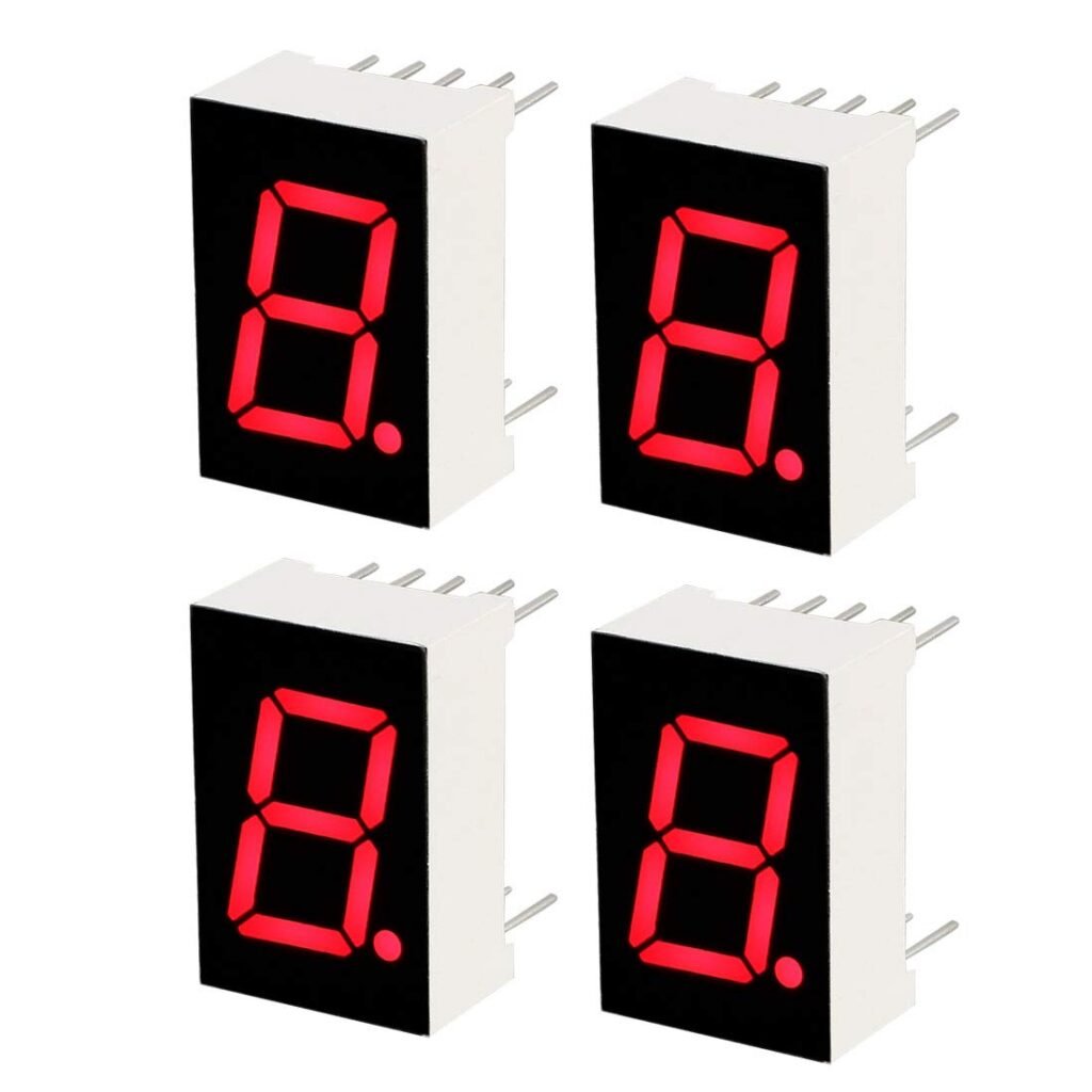
- 7 Segment Display Common Cathode
- NUCLEO-F439ZI
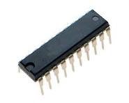
- ATF16V8B-15PU
- Original XGecu T48 [TL866-3G] Programmer
Project Structure
This project uses an STM32CubeIDE-generated firmware project alongside a discrete ATF16V8B PLD design and a 7-segment display interface. The original source walkthrough and code/plugin blocks are preserved below in the Code Walkthrough section.
Hardware Configuration / Pinouts
Overview
This tutorial includes hardware. The original hardware-oriented material from the legacy post is preserved below, including the 7-segment display explanation, ATF16V8B overview, schematic, and IOC/PDF configuration content.
Anatomy of a 7 Segment Display
You will note that there are 7 segments, plus a decimal point LED, but we won’t be using the decimal point LED known as DP.
Each LED segment is labeled from a-g, with the decimal point LED labeled DP.

ATF16V8B – Programmable Logic Device

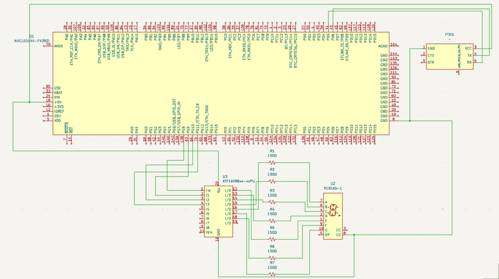
Schematic
Project Setup
WinCUPL Tool Download
WinCUPL v5.30.4 is the tool you will need to download to be able to edit and compile your PLD using the TL866-3G programmer. It has not been updated in a long time, and it does have bugs. There are other tools that might support CUPL, but they are not free. Other languages other than CUPL exist, but for this tutorial, we are going to focus on CUPL. When a PLD file is compiled without errors, WinCUPL will generate a standard JEDEC file which can be fed into your programmer device.
WinCUPL Logic File
Name     Hex_to_7seg_Decoder ;
PartNo   ATF16V8B ;
Date     8/7/2025 ;
Revision 1.0 ;
Designer Engineer ;
Company  X ;
Assembly None ;
Location  ;
Device   virtual ;

/* *************** INPUT PINS *********************/
PIN 1 = I0 ; /* BCD A (LSB)*/
PIN 2 = I1 ; /* BCD B */
PIN 3 = I2 ; /* BCD C */
PIN 4 = I3 ; /* BCD D (MSB)*/


/* *************** OUTPUT PINS ******************** */
PIN 16 = A;	/* Seven segment LED "A" */
PIN 15 = B;	/* Seven segment LED "B" */
PIN 14 = C;	/* Seven segment LED "C" */
PIN 13 = D;	/* Seven segment LED "D" */
PIN 12 = E;	/* Seven segment LED "E" */
PIN 18 = F;	/* Seven segment LED "F" */
PIN 17 = G;	/* Seven segment LED "G" */

FIELD INPUT = [I3,I2,I1,I0]; 	/* input array definition */
FIELD OUTPUT = [A,B,C,D,E,F,G]; 	/* output array definition */
TABLE INPUT => OUTPUT		/* output values not inverted because Common Cathode */
{
'b'0000 => 'b'1111110;	/* Symbol "0" */
'b'0001 => 'b'0110000;	/* Symbol "1" */
'b'0010 => 'b'1101101;	/* Symbol "2" */
'b'0011 => 'b'1111001;	/* Symbol "3" */
'b'0100 => 'b'0110011;	/* Symbol "4" */
'b'0101 => 'b'1011011;	/* Symbol "5" */
'b'0110 => 'b'1011111;	/* Symbol "6" */
'b'0111 => 'b'1110000;	/* Symbol "7" */
'b'1000 => 'b'1111111;	/* Symbol "8" */
'b'1001 => 'b'1110011;	/* Symbol "9" */
'b'1010 => 'b'1110111;	/* Symbol "A" */
'b'1011 => 'b'0011111;	/* Symbol "b" */
'b'1100 => 'b'1001110;	/* Symbol "C" */
'b'1101 => 'b'0111101;	/* Symbol "d" */
'b'1110 => 'b'1001111;	/* Symbol "E" */
'b'1111 => 'b'1000111;	/* Symbol "F" */
}Pinouts & Configurations
This is a generated PDF of all of the settings within the IOC file, which is included below. Parameters that have changed from the default values are highlighted by being in BOLD with an asterisk “*“
Code Walkthrough
main.h
/* USER CODE BEGIN Header */
/**
  ******************************************************************************
  * @file           : main.h
  * @brief          : Header for main.c file.
  *                   This file contains the common defines of the application.
  ******************************************************************************
  * @attention
  *
  * Copyright (c) 2025 STMicroelectronics.
  * All rights reserved.
  *
  * This software is licensed under terms that can be found in the LICENSE file
  * in the root directory of this software component.
  * If no LICENSE file comes with this software, it is provided AS-IS.
  *
  ******************************************************************************
  */
/* USER CODE END Header */

/* Define to prevent recursive inclusion -------------------------------------*/
#ifndef __MAIN_H
#define __MAIN_H

#ifdef __cplusplus
extern "C" {
#endif

/* Includes ------------------------------------------------------------------*/
#include "stm32f4xx_hal.h"

/* Private includes ----------------------------------------------------------*/
/* USER CODE BEGIN Includes */

/* USER CODE END Includes */

/* Exported types ------------------------------------------------------------*/
/* USER CODE BEGIN ET */

/* USER CODE END ET */

/* Exported constants --------------------------------------------------------*/
/* USER CODE BEGIN EC */

/* USER CODE END EC */

/* Exported macro ------------------------------------------------------------*/
/* USER CODE BEGIN EM */

/* USER CODE END EM */

void HAL_TIM_MspPostInit(TIM_HandleTypeDef *htim);

/* Exported functions prototypes ---------------------------------------------*/

/* USER CODE BEGIN EFP */

/* USER CODE END EFP */

/* Private defines -----------------------------------------------------------*/
#define USER_Btn_Pin GPIO_PIN_13
#define USER_Btn_GPIO_Port GPIOC
#define MCO_Pin GPIO_PIN_0
#define MCO_GPIO_Port GPIOH
#define LD1_Pin GPIO_PIN_0
#define LD1_GPIO_Port GPIOB
#define LD3_Pin GPIO_PIN_14
#define LD3_GPIO_Port GPIOB
#define TMS_Pin GPIO_PIN_13
#define TMS_GPIO_Port GPIOA
#define TCK_Pin GPIO_PIN_14
#define TCK_GPIO_Port GPIOA
#define LD2_Pin GPIO_PIN_7
#define LD2_GPIO_Port GPIOB

/* USER CODE BEGIN Private defines */

void _Error_Handler(const char *, int);

#define Error_Handler() _Error_Handler((const char *)__FILE__, __LINE__)
#define REDIRECT_PRINTF

/* USER CODE END Private defines */

#ifdef __cplusplus
}
#endif

#endif /* __MAIN_H */
main.c
/* USER CODE BEGIN Header */
/**
  ******************************************************************************
  * @file           : main.c
  * @brief          : Main program body
  ******************************************************************************
  * @attention
  *
  * Copyright (c) 2025 STMicroelectronics.
  * All rights reserved.
  *
  * This software is licensed under terms that can be found in the LICENSE file
  * in the root directory of this software component.
  * If no LICENSE file comes with this software, it is provided AS-IS.
  *
  ******************************************************************************
  */
/* USER CODE END Header */
/* Includes ------------------------------------------------------------------*/
#include "main.h"

/* Private includes ----------------------------------------------------------*/
/* USER CODE BEGIN Includes */
#include "stdio.h"
#include "stdbool.h"
/* USER CODE END Includes */

/* Private typedef -----------------------------------------------------------*/
/* USER CODE BEGIN PTD */

/* USER CODE END PTD */

/* Private define ------------------------------------------------------------*/
/* USER CODE BEGIN PD */

/* USER CODE END PD */

/* Private macro -------------------------------------------------------------*/
/* USER CODE BEGIN PM */

/* USER CODE END PM */

/* Private variables ---------------------------------------------------------*/
TIM_HandleTypeDef htim1;

UART_HandleTypeDef huart2;

/* USER CODE BEGIN PV */

/* USER CODE END PV */

/* Private function prototypes -----------------------------------------------*/
void SystemClock_Config(void);
static void MX_GPIO_Init(void);
static void MX_USART2_UART_Init(void);
static void MX_TIM1_Init(void);
/* USER CODE BEGIN PFP */

/* USER CODE END PFP */

/* Private user code ---------------------------------------------------------*/
/* USER CODE BEGIN 0 */

#ifdef REDIRECT_PRINTF
#define PUTCHAR_PROTOTYPE int __io_putchar(int ch)
#endif

#ifdef REDIRECT_PRINTF
/**
  * @brief  Retargets the C library printf function to the USART.
  * @param  None
  * @retval None
  */
PUTCHAR_PROTOTYPE
{
  HAL_UART_Transmit(&huart2, (uint8_t *)&ch, 1, 0xFFFF);

  return ch;
}
#endif

void set7SegmentDisplay(uint8_t byte) {

	uint8_t bits[4];
	uint8_t mask = 1; // Bit mask
	GPIO_PinState pinState = GPIO_PIN_RESET;

	printf("byte: %x\r\n", byte);

	for (int i = 0; i < 4; i++) {
	    // Mask each bit in the byte and store it
		bits[i] = (byte >> i) & mask;
		printf("bits[%d]: %x\r\n", i, bits[i]);
	}

	pinState = (bits[0] ? GPIO_PIN_SET : GPIO_PIN_RESET);
	HAL_GPIO_WritePin(GPIOC, GPIO_PIN_8, pinState);

	pinState = (bits[1] ? GPIO_PIN_SET : GPIO_PIN_RESET);
	HAL_GPIO_WritePin(GPIOC, GPIO_PIN_9, pinState);

	pinState = (bits[2] ? GPIO_PIN_SET : GPIO_PIN_RESET);
	HAL_GPIO_WritePin(GPIOC, GPIO_PIN_10, pinState);

	pinState = (bits[3] ? GPIO_PIN_SET : GPIO_PIN_RESET);
	HAL_GPIO_WritePin(GPIOC, GPIO_PIN_11, pinState);

	HAL_Delay(1);

	printf("\n\r\n\r\n");
}

/* USER CODE END 0 */

/**
  * @brief  The application entry point.
  * @retval int
  */
int main(void)
{

  /* USER CODE BEGIN 1 */

  /* USER CODE END 1 */

  /* MCU Configuration--------------------------------------------------------*/

  /* Reset of all peripherals, Initializes the Flash interface and the Systick. */
  HAL_Init();

  /* USER CODE BEGIN Init */

  /* USER CODE END Init */

  /* Configure the system clock */
  SystemClock_Config();

  /* USER CODE BEGIN SysInit */

  /* USER CODE END SysInit */

  /* Initialize all configured peripherals */
  MX_GPIO_Init();
  MX_USART2_UART_Init();
  MX_TIM1_Init();
  /* USER CODE BEGIN 2 */

printf("\x1b[2J\x1b[H");	// Clear the dumb terminal screen

	HAL_TIM_Base_Start_IT(&htim1);
	HAL_TIM_OC_Start(&htim1, TIM_CHANNEL_1);
  /* USER CODE END 2 */

  /* Infinite loop */
  /* USER CODE BEGIN WHILE */
  while (1)
  {
	  for (int i = 0; i < 16; i ++) {
		  set7SegmentDisplay(i);
		  HAL_Delay(1000);
	  }

    /* USER CODE END WHILE */

    /* USER CODE BEGIN 3 */
  }
  /* USER CODE END 3 */
}

/**
  * @brief System Clock Configuration
  * @retval None
  */
void SystemClock_Config(void)
{
  RCC_OscInitTypeDef RCC_OscInitStruct = {0};
  RCC_ClkInitTypeDef RCC_ClkInitStruct = {0};

  /** Configure the main internal regulator output voltage
  */
  __HAL_RCC_PWR_CLK_ENABLE();
  __HAL_PWR_VOLTAGESCALING_CONFIG(PWR_REGULATOR_VOLTAGE_SCALE1);

  /** Initializes the RCC Oscillators according to the specified parameters
  * in the RCC_OscInitTypeDef structure.
  */
  RCC_OscInitStruct.OscillatorType = RCC_OSCILLATORTYPE_HSE;
  RCC_OscInitStruct.HSEState = RCC_HSE_ON;
  RCC_OscInitStruct.PLL.PLLState = RCC_PLL_ON;
  RCC_OscInitStruct.PLL.PLLSource = RCC_PLLSOURCE_HSE;
  RCC_OscInitStruct.PLL.PLLM = 4;
  RCC_OscInitStruct.PLL.PLLN = 180;
  RCC_OscInitStruct.PLL.PLLP = RCC_PLLP_DIV2;
  RCC_OscInitStruct.PLL.PLLQ = 4;
  if (HAL_RCC_OscConfig(&RCC_OscInitStruct) != HAL_OK)
  {
    Error_Handler();
  }

  /** Activate the Over-Drive mode
  */
  if (HAL_PWREx_EnableOverDrive() != HAL_OK)
  {
    Error_Handler();
  }

  /** Initializes the CPU, AHB and APB buses clocks
  */
  RCC_ClkInitStruct.ClockType = RCC_CLOCKTYPE_HCLK|RCC_CLOCKTYPE_SYSCLK
                              |RCC_CLOCKTYPE_PCLK1|RCC_CLOCKTYPE_PCLK2;
  RCC_ClkInitStruct.SYSCLKSource = RCC_SYSCLKSOURCE_PLLCLK;
  RCC_ClkInitStruct.AHBCLKDivider = RCC_SYSCLK_DIV1;
  RCC_ClkInitStruct.APB1CLKDivider = RCC_HCLK_DIV4;
  RCC_ClkInitStruct.APB2CLKDivider = RCC_HCLK_DIV2;

  if (HAL_RCC_ClockConfig(&RCC_ClkInitStruct, FLASH_LATENCY_5) != HAL_OK)
  {
    Error_Handler();
  }
}

/**
  * @brief TIM1 Initialization Function
  * @param None
  * @retval None
  */
static void MX_TIM1_Init(void)
{

  /* USER CODE BEGIN TIM1_Init 0 */

  /* USER CODE END TIM1_Init 0 */

  TIM_ClockConfigTypeDef sClockSourceConfig = {0};
  TIM_MasterConfigTypeDef sMasterConfig = {0};
  TIM_OC_InitTypeDef sConfigOC = {0};
  TIM_BreakDeadTimeConfigTypeDef sBreakDeadTimeConfig = {0};

  /* USER CODE BEGIN TIM1_Init 1 */

  /* USER CODE END TIM1_Init 1 */
  htim1.Instance = TIM1;
  htim1.Init.Prescaler = 0;
  htim1.Init.CounterMode = TIM_COUNTERMODE_UP;
  htim1.Init.Period = 3;
  htim1.Init.ClockDivision = TIM_CLOCKDIVISION_DIV1;
  htim1.Init.RepetitionCounter = 0;
  htim1.Init.AutoReloadPreload = TIM_AUTORELOAD_PRELOAD_DISABLE;
  if (HAL_TIM_Base_Init(&htim1) != HAL_OK)
  {
    Error_Handler();
  }
  sClockSourceConfig.ClockSource = TIM_CLOCKSOURCE_INTERNAL;
  if (HAL_TIM_ConfigClockSource(&htim1, &sClockSourceConfig) != HAL_OK)
  {
    Error_Handler();
  }
  if (HAL_TIM_OC_Init(&htim1) != HAL_OK)
  {
    Error_Handler();
  }
  sMasterConfig.MasterOutputTrigger = TIM_TRGO_RESET;
  sMasterConfig.MasterSlaveMode = TIM_MASTERSLAVEMODE_DISABLE;
  if (HAL_TIMEx_MasterConfigSynchronization(&htim1, &sMasterConfig) != HAL_OK)
  {
    Error_Handler();
  }
  sConfigOC.OCMode = TIM_OCMODE_TOGGLE;
  sConfigOC.Pulse = 3;
  sConfigOC.OCPolarity = TIM_OCPOLARITY_HIGH;
  sConfigOC.OCNPolarity = TIM_OCNPOLARITY_HIGH;
  sConfigOC.OCFastMode = TIM_OCFAST_DISABLE;
  sConfigOC.OCIdleState = TIM_OCIDLESTATE_RESET;
  sConfigOC.OCNIdleState = TIM_OCNIDLESTATE_RESET;
  if (HAL_TIM_OC_ConfigChannel(&htim1, &sConfigOC, TIM_CHANNEL_1) != HAL_OK)
  {
    Error_Handler();
  }
  sBreakDeadTimeConfig.OffStateRunMode = TIM_OSSR_DISABLE;
  sBreakDeadTimeConfig.OffStateIDLEMode = TIM_OSSI_DISABLE;
  sBreakDeadTimeConfig.LockLevel = TIM_LOCKLEVEL_OFF;
  sBreakDeadTimeConfig.DeadTime = 0;
  sBreakDeadTimeConfig.BreakState = TIM_BREAK_DISABLE;
  sBreakDeadTimeConfig.BreakPolarity = TIM_BREAKPOLARITY_HIGH;
  sBreakDeadTimeConfig.AutomaticOutput = TIM_AUTOMATICOUTPUT_DISABLE;
  if (HAL_TIMEx_ConfigBreakDeadTime(&htim1, &sBreakDeadTimeConfig) != HAL_OK)
  {
    Error_Handler();
  }
  /* USER CODE BEGIN TIM1_Init 2 */

  /* USER CODE END TIM1_Init 2 */
  HAL_TIM_MspPostInit(&htim1);

}

/**
  * @brief USART2 Initialization Function
  * @param None
  * @retval None
  */
static void MX_USART2_UART_Init(void)
{

  /* USER CODE BEGIN USART2_Init 0 */

  /* USER CODE END USART2_Init 0 */

  /* USER CODE BEGIN USART2_Init 1 */

  /* USER CODE END USART2_Init 1 */
  huart2.Instance = USART2;
  huart2.Init.BaudRate = 19200;
  huart2.Init.WordLength = UART_WORDLENGTH_8B;
  huart2.Init.StopBits = UART_STOPBITS_1;
  huart2.Init.Parity = UART_PARITY_NONE;
  huart2.Init.Mode = UART_MODE_TX_RX;
  huart2.Init.HwFlowCtl = UART_HWCONTROL_NONE;
  huart2.Init.OverSampling = UART_OVERSAMPLING_16;
  if (HAL_UART_Init(&huart2) != HAL_OK)
  {
    Error_Handler();
  }
  /* USER CODE BEGIN USART2_Init 2 */

  /* USER CODE END USART2_Init 2 */

}

/**
  * @brief GPIO Initialization Function
  * @param None
  * @retval None
  */
static void MX_GPIO_Init(void)
{
  GPIO_InitTypeDef GPIO_InitStruct = {0};
  /* USER CODE BEGIN MX_GPIO_Init_1 */

  /* USER CODE END MX_GPIO_Init_1 */

  /* GPIO Ports Clock Enable */
  __HAL_RCC_GPIOC_CLK_ENABLE();
  __HAL_RCC_GPIOH_CLK_ENABLE();
  __HAL_RCC_GPIOB_CLK_ENABLE();
  __HAL_RCC_GPIOE_CLK_ENABLE();
  __HAL_RCC_GPIOA_CLK_ENABLE();
  __HAL_RCC_GPIOD_CLK_ENABLE();

  /*Configure GPIO pin Output Level */
  HAL_GPIO_WritePin(GPIOB, LD1_Pin|LD3_Pin|LD2_Pin, GPIO_PIN_RESET);

  /*Configure GPIO pin Output Level */
  HAL_GPIO_WritePin(GPIOC, GPIO_PIN_8|GPIO_PIN_9|GPIO_PIN_10|GPIO_PIN_11, GPIO_PIN_RESET);

  /*Configure GPIO pin : USER_Btn_Pin */
  GPIO_InitStruct.Pin = USER_Btn_Pin;
  GPIO_InitStruct.Mode = GPIO_MODE_IT_RISING;
  GPIO_InitStruct.Pull = GPIO_NOPULL;
  HAL_GPIO_Init(USER_Btn_GPIO_Port, &GPIO_InitStruct);

  /*Configure GPIO pins : LD1_Pin LD3_Pin LD2_Pin */
  GPIO_InitStruct.Pin = LD1_Pin|LD3_Pin|LD2_Pin;
  GPIO_InitStruct.Mode = GPIO_MODE_OUTPUT_PP;
  GPIO_InitStruct.Pull = GPIO_NOPULL;
  GPIO_InitStruct.Speed = GPIO_SPEED_FREQ_LOW;
  HAL_GPIO_Init(GPIOB, &GPIO_InitStruct);

  /*Configure GPIO pins : PC8 PC9 PC10 PC11 */
  GPIO_InitStruct.Pin = GPIO_PIN_8|GPIO_PIN_9|GPIO_PIN_10|GPIO_PIN_11;
  GPIO_InitStruct.Mode = GPIO_MODE_OUTPUT_PP;
  GPIO_InitStruct.Pull = GPIO_NOPULL;
  GPIO_InitStruct.Speed = GPIO_SPEED_FREQ_LOW;
  HAL_GPIO_Init(GPIOC, &GPIO_InitStruct);

  /* USER CODE BEGIN MX_GPIO_Init_2 */

  /* USER CODE END MX_GPIO_Init_2 */
}

/* USER CODE BEGIN 4 */


/**
 * @brief  This function is executed in case of error occurrence.
 * @param  file: The file name as string.
 * @param  line: The line in file as a number.
 * @retval None
 */
void _Error_Handler(const char *file, int line)
{
	/* USER CODE BEGIN Error_Handler_Debug */
	__disable_irq();
#ifdef REDIRECT_PRINTF
	char buf[80];
	sprintf(buf, "Trapped in _Error_Handler().  Called from: %s, line: %d\r\n", file, line);
	printf(buf);
#endif
	/* User can add his own implementation to report the HAL error return state */
	while(1)
	{
	}
}

/* USER CODE END 4 */

#ifdef  USE_FULL_ASSERT
/**
  * @brief  Reports the name of the source file and the source line number
  *         where the assert_param error has occurred.
  * @param  file: pointer to the source file name
  * @param  line: assert_param error line source number
  * @retval None
  */
void assert_failed(uint8_t *file, uint32_t line)
{
  /* USER CODE BEGIN 6 */
  /* User can add his own implementation to report the file name and line number,
     ex: printf("Wrong parameters value: file %s on line %d\r\n", file, line) */
  /* USER CODE END 6 */
}
#endif /* USE_FULL_ASSERT */
If you have questions or run into trouble getting the boards programmed and talking to each other, post in the Tutorial Support forum and I will work through it with you. If project source is not linked in the tutorial, it may be available on request — use the email contact option in the site footer.