Overview
This tutorial covers STM32 SPI EEPROM 25AA040A read and write operations using an STM32 microcontroller. The 25AA040A is a 512KB device organized into 32 pages of 16 bytes each. Multi-byte writes must stay within page boundaries to avoid data corruption, and each write cycle requires either a delay or status polling before the next operation begins. By the end of this tutorial you will be able to reliably store and retrieve data using SPI EEPROM in your STM32 projects.
Device Characteristics and Datasheet Notes
The following was taken from the datasheet for this 25AA040A EEPROM:
NOTE:Page write operations are limited to
writing bytes within a single physical page,
regardless of the number of bytes
actually being written. Physical page
boundaries start at addresses that are
integer multiples of the page buffer size
(or âpage size’) and end at addresses that
are integer multiples of page size â 1. If a
Page Write command attempts to write
across a physical page boundary, the
result is that the data wrap around to the
beginning of the current page (overwriting
data previously stored there), instead of
being written to the next page as might be
expected. It is therefore necessary for the
application software to prevent page write
operations that would attempt to cross a
page boundary.
All of these limitations pertaining to writes are documented in the datasheet linked below.
This tutorial assumes you have working knowledge of STM32CubeIDE. Although, if you do not have prior working knowledge using STM32CubeIDE, then you should probably click on this link first, as I don’t currently have a tutorial for that topic: STM32CubeIDE Tutorial
What You Will Learn
- How to interface an STM32 MCU with a 25AA040A SPI EEPROM.
- How page boundaries and write-complete polling affect EEPROM access logic.
- How to configure STM32CubeIDE and SPI signals for this project.
- How to read, write, and verify EEPROM data in firmware.
- How to inspect the SPI transactions with a logic analyzer.
Prerequisites
This tutorial assumes you have working knowledge of STM32CubeIDE. Although, if you do not have prior working knowledge using STM32CubeIDE, then you should probably click on this link first, as I don’t currently have a tutorial for that topic: STM32CubeIDE Tutorial
Materials List
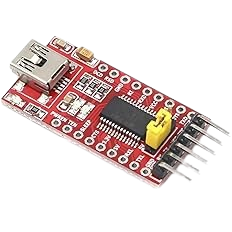
- FTDI to USB
- STM32F103C8TX Be careful when buying cheaper versions to get more boards for less money, as they might not be true STM chips and these won’t work with STM32CubeIDE. Always look at the label on the CPU make sure you see the STM logo.

- ST-Link V2 Emulator Downloader Programmer
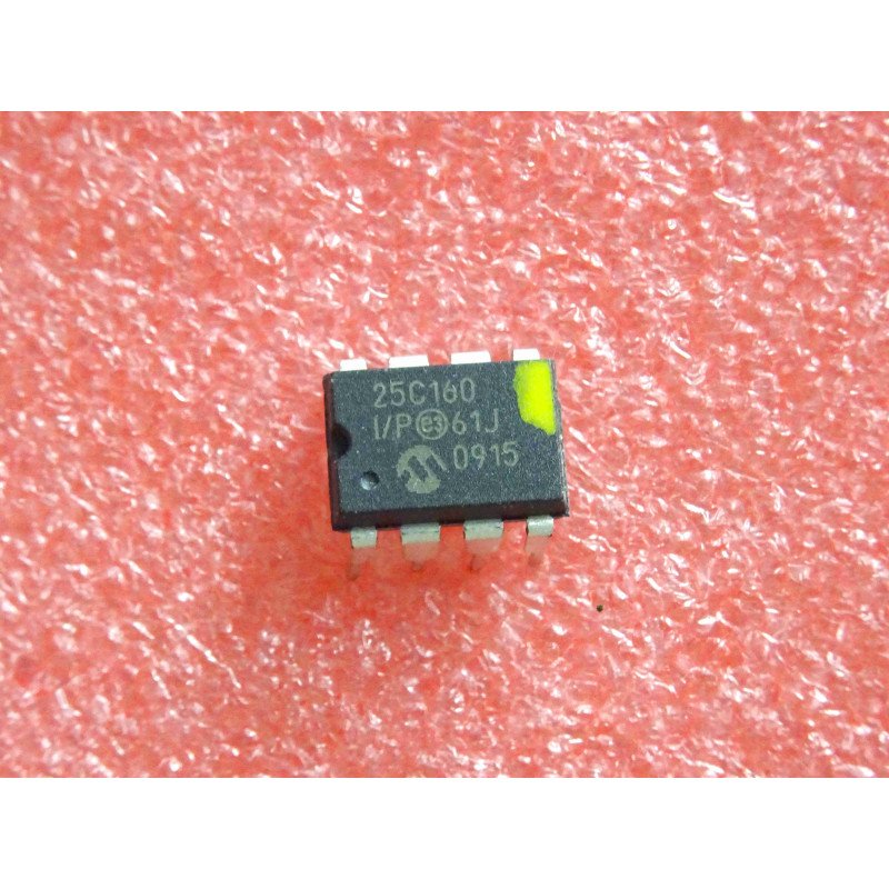
- SPI EEPROM 25AA040A You can find the datasheet on this EEPROM here: 25AA040A
- Logic 8 – Saleae 8-Channel Logic Analyzer
- Breadboards Kit Include 2PCS 830 Point 2PCS 400 Point Solderless Breadboards
Project Structure
This tutorial focuses on the main application and EEPROM driver source files rather than a full project tree listing. The core files discussed below are main.h, main.c, EEPROM_25AA40A.h, and EEPROM_25AA40A.c.
Hardware Configuration / Pinouts
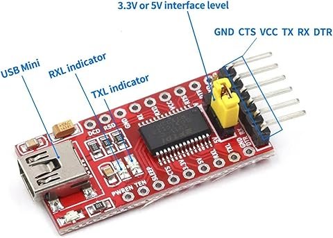
FTDI Pinouts
FTDI to USB Pinout from right to left
- Pin 1 – GND
- Pin 2 – CTS
- Pin 3 – VCC
- Pin 4 – TX
- Pin 5 – RX
- Pin 6 – DTR
- USB Mini – Connect to PC via USB cable
Make sure the jumper is set for 5v or 3v which ever is being used to power the FTDI device. If we look below at the schematic, it is showing in this case as 5v.
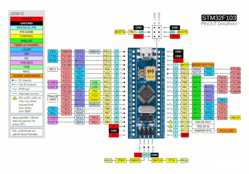
STM32F103C8Tx Pin Diagram
I used a STM32F103C8TX for this project, however any of the STM32 boards will most likely work, including Nucleo boards.
Schematic
The schematic below shows the connections for this project, please note the the label VDD/Pin 24 does not match the pinouts listed above. For this project please refer to the Header Pins for +5v.
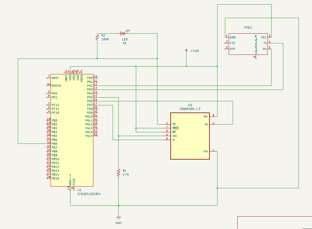
*** NOTE: I had to add a 4.7K resistor R1 to the SPI CLK, otherwise I had issues. On other STM boards, if you can set pullup/pulldown resistors via IOC file configurations, then a physical resistor is not necessary
Project Setup
CubeIDE Configuration
- PA2 – USART TX
- PA3 – USART TX
- PA5 – SPI CLK
- PA6 – MISO (Master In/Slave Out)
- PA7 – MOSI (Master Out/Slave In)
- PA13 – SWDIO – Debug Serial Wire IO
- PA14 -SWCLK – Debug Clock
- PB6 – Chip Select for the EEPROM
The following parameters must be configured and setup under the “SYS” menu option before your first attempt to upload and/or debug code. Others have experienced board lock-up without these being setup. If you do happen to lock-up your STM32F103C8T6 board, you can google how to erase the board memory to fix this issue.
Make sure to set the Baud rate to match that of your terminal emulator software. They must match or you will get garage characters or no characters being displayed.
Keep the clock settings at the default values, as we are not dependent upon it for this project.
Code Walkthrough
main.h
 /* USER CODE BEGIN Header */
/**
  ******************************************************************************
  * @file           : main.h
  * @brief          : Header for main.c file.
  *                   This file contains the common defines of the application.
  ******************************************************************************
  * @attention
  *
  * Copyright (c) 2024 STMicroelectronics.
  * All rights reserved.
  *
  * This software is licensed under terms that can be found in the LICENSE file
  * in the root directory of this software component.
  * If no LICENSE file comes with this software, it is provided AS-IS.
  *
  ******************************************************************************
  */
/* USER CODE END Header */

/* Define to prevent recursive inclusion -------------------------------------*/
#ifndef __MAIN_H
#define __MAIN_H

#ifdef __cplusplus
extern "C" {
#endif

/* Includes ------------------------------------------------------------------*/
#include "stm32f1xx_hal.h"

/* Private includes ----------------------------------------------------------*/
/* USER CODE BEGIN Includes */

/* USER CODE END Includes */

/* Exported types ------------------------------------------------------------*/
/* USER CODE BEGIN ET */

/* USER CODE END ET */

/* Exported constants --------------------------------------------------------*/
/* USER CODE BEGIN EC */

/* USER CODE END EC */

/* Exported macro ------------------------------------------------------------*/
/* USER CODE BEGIN EM */

/* USER CODE END EM */

/* Exported functions prototypes ---------------------------------------------*/
void Error_Handler(void);

/* USER CODE BEGIN EFP */

/* USER CODE END EFP */

/* Private defines -----------------------------------------------------------*/

/* USER CODE BEGIN Private defines */
#define REDIRECT_PRINTF

void _Error_Handler(const char *, int);

#define Error_Handler() _Error_Handler((const char *)__FILE__, __LINE__)
/* USER CODE END Private defines */

#ifdef __cplusplus
}
#endif

#endif /* __MAIN_H */
main.c
/* USER CODE BEGIN Header */
/**
  ******************************************************************************
  * @file           : main.c
  * @brief          : Main program body
  ******************************************************************************
  * @attention
  *
  * Copyright (c) 2024 STMicroelectronics.
  * All rights reserved.
  *
  * This software is licensed under terms that can be found in the LICENSE file
  * in the root directory of this software component.
  * If no LICENSE file comes with this software, it is provided AS-IS.
  *
  ******************************************************************************
  */
/* USER CODE END Header */
/* Includes ------------------------------------------------------------------*/
#include "main.h"

/* Private includes ----------------------------------------------------------*/
/* USER CODE BEGIN Includes */
#include "stdio.h"
#include "string.h"
#include "EEPROM_25AA40A.h"
/* USER CODE END Includes */

/* Private typedef -----------------------------------------------------------*/
/* USER CODE BEGIN PTD */

/* USER CODE END PTD */

/* Private define ------------------------------------------------------------*/
/* USER CODE BEGIN PD */

/* USER CODE END PD */

/* Private macro -------------------------------------------------------------*/
/* USER CODE BEGIN PM */

/* USER CODE END PM */

/* Private variables ---------------------------------------------------------*/
SPI_HandleTypeDef hspi1;

UART_HandleTypeDef huart2;

/* USER CODE BEGIN PV */

/* USER CODE END PV */

/* Private function prototypes -----------------------------------------------*/
void SystemClock_Config(void);
static void MX_GPIO_Init(void);
static void MX_SPI1_Init(void);
static void MX_USART2_UART_Init(void);
/* USER CODE BEGIN PFP */

/* USER CODE END PFP */In the below section of code, we are setting up to redirect PRINTF output to USART2
* Private user code ---------------------------------------------------------*/
/* USER CODE BEGIN 0 */
#ifdef REDIRECT_PRINTF
#define PUTCHAR_PROTOTYPE int __io_putchar(int ch)
#endif

#ifdef REDIRECT_PRINTF
/**
  * @brief  Retargets the C library printf function to the USART.
  * @param  None
  * @retval None
  */
PUTCHAR_PROTOTYPE
{
  /* Place your implementation of fputc here */
  /* e.g. write a character to the USART2 and Loop until the end of transmission */
  HAL_UART_Transmit(&huart2, (uint8_t *)&ch, 1, 0xFFFF);

  return ch;
}
#endifThis is the function that will execirse writing and reading from the EEPROM. This code will call the lower level functions that will actually perform the writing and reading.
Note that on line 101, I’m setting the address for writes/reads to be 0x10A. This could have been any address within 0-511K. We could have set it to 0x00, or anywhere in between, as this was just an example.
You just have to remain within the boundaries of the EEPROM iteself. If you’re writing towards then end of memory, what you write needs to fit before the 511 Memory address.
void testSPI_25AA40A() {
	HAL_StatusTypeDef halStatus = HAL_OK;
	char spi_buf[100];
	uint16_t addr;

	halStatus = eepromInit(&hspi1);

	if (halStatus != HAL_OK) {
		Error_Handler();
	}

	memset(spi_buf, 0x00, sizeof(spi_buf));

	sprintf(spi_buf, "Now is the time for all good people to provide lots of snacks for their pets!!!");

	int len = strlen(spi_buf) + 1;	// Add 1 to take into account the '/0' NULL byte.

	// Set starting address
//	addr = 0x01E7;
	addr = 0x10A;

	printf("Writing %d Bytes to Address: 0x%04x\r\n", len, addr);

	halStatus = eepromWrite(addr, (uint8_t *) &spi_buf, len);

	if (halStatus != HAL_OK) {
		Error_Handler();
	}

	memset(spi_buf, 0x00, sizeof(spi_buf));

	printf("Reading %d Bytes from Address: 0x%04x\r\n", len, addr);

	halStatus = eepromRead(addr, (uint8_t *) &spi_buf, len);

	if (halStatus != HAL_OK) {
		Error_Handler();
	}

	printf("%s\r\n", spi_buf);
}
/* USER CODE END 0 */
/**
  * @brief  The application entry point.
  * @retval int
  */
int main(void)
{

  /* USER CODE BEGIN 1 */

  /* USER CODE END 1 */

  /* MCU Configuration--------------------------------------------------------*/

  /* Reset of all peripherals, Initializes the Flash interface and the Systick. */
  HAL_Init();

  /* USER CODE BEGIN Init */

  /* USER CODE END Init */

  /* Configure the system clock */
  SystemClock_Config();

  /* USER CODE BEGIN SysInit */

  /* USER CODE END SysInit */

  /* Initialize all configured peripherals */
  MX_GPIO_Init();
  MX_SPI1_Init();
  MX_USART2_UART_Init();
  /* USER CODE BEGIN 2 */
  printf("\x1b[2J\x1b[H");	// Clear the dumb terminal screen
  printf("Hello!!!\r\n");

  /* USER CODE END 2 */

  /* Infinite loop */
  /* USER CODE BEGIN WHILE */
  while (1)
  {
	  testSPI_25AA40A();
	  HAL_Delay(5000);
    /* USER CODE END WHILE */

    /* USER CODE BEGIN 3 */
  }
  /* USER CODE END 3 */
}
The code below is auto generated by STM32CubeIDE when you save the contects of the IOC file.
/**
  * @brief System Clock Configuration
  * @retval None
  */
void SystemClock_Config(void)
{
  RCC_OscInitTypeDef RCC_OscInitStruct = {0};
  RCC_ClkInitTypeDef RCC_ClkInitStruct = {0};

  /** Initializes the RCC Oscillators according to the specified parameters
  * in the RCC_OscInitTypeDef structure.
  */
  RCC_OscInitStruct.OscillatorType = RCC_OSCILLATORTYPE_HSI;
  RCC_OscInitStruct.HSIState = RCC_HSI_ON;
  RCC_OscInitStruct.HSICalibrationValue = RCC_HSICALIBRATION_DEFAULT;
  RCC_OscInitStruct.PLL.PLLState = RCC_PLL_ON;
  RCC_OscInitStruct.PLL.PLLSource = RCC_PLLSOURCE_HSI_DIV2;
  RCC_OscInitStruct.PLL.PLLMUL = RCC_PLL_MUL16;
  if (HAL_RCC_OscConfig(&RCC_OscInitStruct) != HAL_OK)
  {
    Error_Handler();
  }

  /** Initializes the CPU, AHB and APB buses clocks
  */
  RCC_ClkInitStruct.ClockType = RCC_CLOCKTYPE_HCLK|RCC_CLOCKTYPE_SYSCLK
                              |RCC_CLOCKTYPE_PCLK1|RCC_CLOCKTYPE_PCLK2;
  RCC_ClkInitStruct.SYSCLKSource = RCC_SYSCLKSOURCE_PLLCLK;
  RCC_ClkInitStruct.AHBCLKDivider = RCC_SYSCLK_DIV1;
  RCC_ClkInitStruct.APB1CLKDivider = RCC_HCLK_DIV2;
  RCC_ClkInitStruct.APB2CLKDivider = RCC_HCLK_DIV1;

  if (HAL_RCC_ClockConfig(&RCC_ClkInitStruct, FLASH_LATENCY_2) != HAL_OK)
  {
    Error_Handler();
  }
}

/**
  * @brief SPI1 Initialization Function
  * @param None
  * @retval None
  */
static void MX_SPI1_Init(void)
{

  /* USER CODE BEGIN SPI1_Init 0 */

  /* USER CODE END SPI1_Init 0 */

  /* USER CODE BEGIN SPI1_Init 1 */

  /* USER CODE END SPI1_Init 1 */
  /* SPI1 parameter configuration*/
  hspi1.Instance = SPI1;
  hspi1.Init.Mode = SPI_MODE_MASTER;
  hspi1.Init.Direction = SPI_DIRECTION_2LINES;
  hspi1.Init.DataSize = SPI_DATASIZE_8BIT;
  hspi1.Init.CLKPolarity = SPI_POLARITY_LOW;
  hspi1.Init.CLKPhase = SPI_PHASE_1EDGE;
  hspi1.Init.NSS = SPI_NSS_SOFT;
  hspi1.Init.BaudRatePrescaler = SPI_BAUDRATEPRESCALER_128;
  hspi1.Init.FirstBit = SPI_FIRSTBIT_MSB;
  hspi1.Init.TIMode = SPI_TIMODE_DISABLE;
  hspi1.Init.CRCCalculation = SPI_CRCCALCULATION_DISABLE;
  hspi1.Init.CRCPolynomial = 10;
  if (HAL_SPI_Init(&hspi1) != HAL_OK)
  {
    Error_Handler();
  }
  /* USER CODE BEGIN SPI1_Init 2 */

  /* USER CODE END SPI1_Init 2 */

}

/**
  * @brief USART2 Initialization Function
  * @param None
  * @retval None
  */
static void MX_USART2_UART_Init(void)
{

  /* USER CODE BEGIN USART2_Init 0 */

  /* USER CODE END USART2_Init 0 */

  /* USER CODE BEGIN USART2_Init 1 */

  /* USER CODE END USART2_Init 1 */
  huart2.Instance = USART2;
  huart2.Init.BaudRate = 19200;
  huart2.Init.WordLength = UART_WORDLENGTH_8B;
  huart2.Init.StopBits = UART_STOPBITS_1;
  huart2.Init.Parity = UART_PARITY_NONE;
  huart2.Init.Mode = UART_MODE_TX_RX;
  huart2.Init.HwFlowCtl = UART_HWCONTROL_NONE;
  huart2.Init.OverSampling = UART_OVERSAMPLING_16;
  if (HAL_UART_Init(&huart2) != HAL_OK)
  {
    Error_Handler();
  }
  /* USER CODE BEGIN USART2_Init 2 */

  /* USER CODE END USART2_Init 2 */

}

/**
  * @brief GPIO Initialization Function
  * @param None
  * @retval None
  */
static void MX_GPIO_Init(void)
{
  GPIO_InitTypeDef GPIO_InitStruct = {0};
/* USER CODE BEGIN MX_GPIO_Init_1 */
/* USER CODE END MX_GPIO_Init_1 */

  /* GPIO Ports Clock Enable */
  __HAL_RCC_GPIOA_CLK_ENABLE();
  __HAL_RCC_GPIOB_CLK_ENABLE();

  /*Configure GPIO pin Output Level */
  HAL_GPIO_WritePin(GPIOB, GPIO_PIN_6, GPIO_PIN_RESET);

  /*Configure GPIO pin : PB6 */
  GPIO_InitStruct.Pin = GPIO_PIN_6;
  GPIO_InitStruct.Mode = GPIO_MODE_OUTPUT_PP;
  GPIO_InitStruct.Pull = GPIO_NOPULL;
  GPIO_InitStruct.Speed = GPIO_SPEED_FREQ_LOW;
  HAL_GPIO_Init(GPIOB, &GPIO_InitStruct);

/* USER CODE BEGIN MX_GPIO_Init_2 */
/* USER CODE END MX_GPIO_Init_2 */
}

/* USER CODE BEGIN 4 */
/**
 * @brief  This function is executed in case of error occurrence.
 * @param  file: The file name as string.
 * @param  line: The line in file as a number.
 * @retval None
 */
void _Error_Handler(const char *file, int line)
{
	/* USER CODE BEGIN Error_Handler_Debug */
#ifdef REDIRECT_PRINTF
	char buf[80];
	sprintf(buf, "Trapped in Error_Handler().  Called from: %s, line: %d\r\n", file, line);
	printf(buf);
#endif
	/* User can add his own implementation to report the HAL error return state */
	while(1)
	{
	}
	/* USER CODE END Error_Handler_Debug */
}
/* USER CODE END 4 */

#ifdef  USE_FULL_ASSERT
/**
  * @brief  Reports the name of the source file and the source line number
  *         where the assert_param error has occurred.
  * @param  file: pointer to the source file name
  * @param  line: assert_param error line source number
  * @retval None
  */
void assert_failed(uint8_t *file, uint32_t line)
{
  /* USER CODE BEGIN 6 */
  /* User can add his own implementation to report the file name and line number,
     ex: printf("Wrong parameters value: file %s on line %d\r\n", file, line) */
  /* USER CODE END 6 */
}
#endif /* USE_FULL_ASSERT */
EEPROM_25AA40A.h
The following include file is needed to support interfacing with the 512KB SPI EEPROM 25AA040A
/*
 * EEPROM_25AA40A.h
 *
 *  Created on: Oct 6, 2024
 *      Author: jpgroulx
 */

#ifndef EEPROM_25AA40A_H_
#define EEPROM_25AA40A_H_

#define EEPROM_SIZE	0x0200			// EEPROM Size 512 bytes x 8 bits (4Kbits)
#define EEPROM_PAGE_SIZE	0x10	// Page size 16 bytes
#define EEPROM_PAGE_NUM		0x20	// Number of pages 32

HAL_StatusTypeDef eepromInit(SPI_HandleTypeDef *hi2c);
HAL_StatusTypeDef eepromBus_Write(uint16_t MemAddr, uint8_t *pData, uint16_t Len);
HAL_StatusTypeDef eepromBus_Read(uint16_t MemAddr, uint8_t *pData, uint16_t Len);

HAL_StatusTypeDef eepromRead(uint16_t MemAddr, uint8_t *pData, uint16_t Len);
HAL_StatusTypeDef eepromWrite(uint16_t MemAddr, uint8_t *value, uint16_t Len);

uint8_t eepromEraseChip(void);
uint8_t eepromFillPage(uint16_t Page, uint8_t Val);
#endif /* EEPROM_25AA40A_H_ */
EEPROM_25AA40A.c
The following source code is the device driver needed to interface with the 512KB SPI EEPROM 25AA040A.
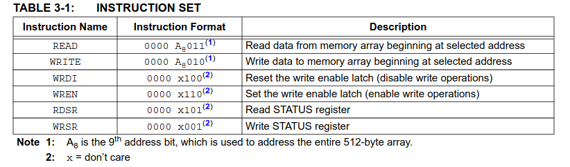
If we look at lines 127-135 we can see how to take bit A8 from the address which we are intending to write to. We have to translate this into what the EEPROM requires for writing/reading above 0xff.
In table 3-1 below, you see that A8 is prepended to the READ/WRITE command MSB bit.
/*
* EEPROM_25AA40A.c
*
* Created on: Oct 6, 2024
* Author: jpgroulx
*/
#include "main.h"
#include "EEPROM_25AA40A.h"
#include "stdio.h"
#include "math.h"
// 25AA040A instructions
const uint8_t EEPROM_READ = 0b00000011;
const uint8_t EEPROM_WRITE = 0b00000010;
const uint8_t EEPROM_WRDI = 0b00000100;
const uint8_t EEPROM_WREN = 0b00000110;
const uint8_t EEPROM_RDSR = 0b00000101;
const uint8_t EEPROM_WRSR = 0b00000001;
SPI_HandleTypeDef *hspi;
HAL_StatusTypeDef eepromInit(SPI_HandleTypeDef *spi) {
HAL_StatusTypeDef halStatus = HAL_OK;
char uart_buf[50];
hspi = spi;
// Test CS Pin be setting it low
HAL_GPIO_WritePin(GPIOB, GPIO_PIN_6, GPIO_PIN_RESET);
HAL_Delay(500);
// CS pin should default high
HAL_GPIO_WritePin(GPIOB, GPIO_PIN_6, GPIO_PIN_SET);
// Say something
sprintf(uart_buf, "\r\n\r\nSPI Test\r\n");
printf(uart_buf);
return(halStatus);
}
/*
Page write operations are limited to
writing bytes within a single physical page,
regardless of the number of bytes
actually being written. Physical page
boundaries start at addresses that are
integer multiples of the page buffer size
(or âpage size') and, end at addresses that
are integer multiples of page size â 1. If a
Page Write command attempts to write
across a physical page boundary, the
result is that the data wraps around to the
beginning of the current page (overwriting
data previously stored there), instead of
being written to the next page as might be
expected. It is therefore necessary for the
application software to prevent page write
operations that would attempt to cross a
page boundary.
*/
/**
* @brief SPI Bus Write 16bit
* @retval HAL_StatusTypeDef
* @param memAddr Internal memory address
* @param pData Pointer to data buffer
* @param Len Amount of data to be Write
*/
HAL_StatusTypeDef eepromBus_Write(uint16_t memAddr, uint8_t *pData, uint16_t len)
{
HAL_StatusTypeDef halStatus = HAL_OK;
uint8_t wip;
char uart_buf[50];
char spi_buf[20];
uint8_t writeCmd;
uint8_t writeAddr;
printf("Preparing to write %d bytes\r\n", len);
// Enable write enable latch (allow write operations)
HAL_GPIO_WritePin(GPIOB, GPIO_PIN_6, GPIO_PIN_RESET);
halStatus = HAL_SPI_Transmit(hspi, (uint8_t *)&EEPROM_WREN, 1, 100);
if (halStatus != HAL_OK) {
Error_Handler();
}
HAL_GPIO_WritePin(GPIOB, GPIO_PIN_6, GPIO_PIN_SET);
// Read status register
HAL_GPIO_WritePin(GPIOB, GPIO_PIN_6, GPIO_PIN_RESET);
halStatus = HAL_SPI_Transmit(hspi, (uint8_t *)&EEPROM_RDSR, 1, 100);
if (halStatus != HAL_OK) {
Error_Handler();
}
halStatus = HAL_SPI_Receive(hspi, (uint8_t *)spi_buf, 1, 100);
if (halStatus != HAL_OK) {
Error_Handler();
}
HAL_GPIO_WritePin(GPIOB, GPIO_PIN_6, GPIO_PIN_SET);
// Print out status register
char status[20];
if (spi_buf[0] == 0x02) {
sprintf(status, "True");
} else {
sprintf(status, "False");
}
sprintf(uart_buf,
"Status: 0x%02x WEL = %s \r\n",
(unsigned int)spi_buf[0], status);
printf(uart_buf);
HAL_GPIO_WritePin(GPIOB, GPIO_PIN_6, GPIO_PIN_RESET);
/* {A8=?} ?010 EEPROM_WRITE: Write data from memory array beginning at selected address.
The LSB of the upper address or A8, is merged into command byte.
Since this EEPROM can address up to 512 Bytes of memory, we need a way to indicate addresses above 0xFF
By shifting the A8 Bit from the address into the writeCMD in the upper bit. This allows the EEPROM to access beyond
0xFF upwards of 0x1FF or 0x0000 thru 0x01FF (0-511)
*/
/* 0000 0001 0000 0010 >> 0000 0000 0000 1010 */
writeCmd = (memAddr & 0x0f00) >> 5;
writeCmd |= EEPROM_WRITE;
halStatus = HAL_SPI_Transmit(hspi, (uint8_t *) &writeCmd, 1, 100);
if (halStatus != HAL_OK) {
Error_Handler();
}
//send lower 8 bits of address
writeAddr = (memAddr & 0x000000ff);
halStatus = HAL_SPI_Transmit(hspi, (uint8_t *) &writeAddr, 1, 100);
if (halStatus != HAL_OK) {
Error_Handler();
}
halStatus = HAL_SPI_Transmit(hspi, (uint8_t *) pData, len, 100);
if (halStatus != HAL_OK) {
Error_Handler();
}
HAL_GPIO_WritePin(GPIOB, GPIO_PIN_6, GPIO_PIN_SET);
/* The Write-In-Process (WIP) bit indicates whether the
25XX040A is busy with a write operation. When set to
a â1', a write is in progress, when set to a â0', no write
is in progress.
*/
// Wait until WIP bit is cleared
wip = 1;
while (wip)
{
// Read status register
HAL_GPIO_WritePin(GPIOB, GPIO_PIN_6, GPIO_PIN_RESET);
halStatus = HAL_SPI_Transmit(hspi, (uint8_t *)&EEPROM_RDSR, 1, 100);
if (halStatus != HAL_OK) {
Error_Handler();
}
halStatus = HAL_SPI_Receive(hspi, (uint8_t *)spi_buf, 1, 100);
if (halStatus != HAL_OK) {
Error_Handler();
}
HAL_GPIO_WritePin(GPIOB, GPIO_PIN_6, GPIO_PIN_SET);
// Mask out WIP bit
wip = spi_buf[0] & 0b00000001;
printf("wip status = 0x%02x\r\n", wip);
}
printf("Wrote %d bytes\r\n", len);
return halStatus;
}
/**
* @brief SPI Bus Read 16bits
* @retval HAL_StatusTypeDef
* @param MemAddr Internal memory address
* @param pData Pointer to data buffer
* @param Len Amount of data to be read
*/
HAL_StatusTypeDef eepromBus_Read(uint16_t memAddr, uint8_t *pData, uint16_t Len)
{
HAL_StatusTypeDef halStatus = HAL_OK;
uint8_t readCmd;
uint8_t readAddr;
char buf[80];
printf("Preparing to read %d bytes\r\n", Len);
HAL_GPIO_WritePin(GPIOB, GPIO_PIN_6, GPIO_PIN_RESET);
/* {A8=?} ?011 EEPROM_READ: Read data from memory array beginning at selected address.
The LSB of the upper address or A8, is merged into the command byte.
Since this EEPROM can address up to 512 Bytes of memory, we need a way to indicate addresses
above 0xFF. By shifting the A8 Bit from the address into the ReadCMD in the upper bit.
This allows the EEPROM to access beyond 0xFF upwards of 0x1FF or 0x0000 thru 0x01FF (0-511)
*/
/* 0000 0001 0000 0011 >> 0000 0000 0000 1011 */
readCmd = (memAddr & 0x0f00) >> 5;
readCmd |= EEPROM_READ;
halStatus = HAL_SPI_Transmit(hspi, (uint8_t *)&readCmd, 1, 100);
if (halStatus != HAL_OK) {
Error_Handler();
}
//send lower 8 bits of address
readAddr = (memAddr & 0x000000ff);
halStatus = HAL_SPI_Transmit(hspi, (uint8_t *)&readAddr, 1, 100);
if (halStatus != HAL_OK) {
Error_Handler();
}
halStatus = HAL_SPI_Receive(hspi, (uint8_t *)pData, Len, 100);
if (halStatus != HAL_OK) {
Error_Handler();
}
HAL_GPIO_WritePin(GPIOB, GPIO_PIN_6, GPIO_PIN_SET);
printf("Read %d bytes\r\n", Len);
return halStatus;
}
/**
* @brief Sequential read from selected memory address with number of byte
* @retval HAL_StatusTypeDef
* @param MemAddr Memory address to start read from
* @param pData Pointer to data
* @param Len Number of byte to read
*/
uint8_t eepromRead(uint16_t memAddr, uint8_t *pData, uint16_t Len)
{
HAL_StatusTypeDef halStatus = HAL_OK;
if (halStatus == HAL_OK && Len > 0) {
/* Read the remaining data */
halStatus = eepromBus_Read(memAddr, pData, Len);
if (halStatus != HAL_OK) {
Error_Handler();
}
}
return halStatus;
}
/**
* @brief Write data into EEPROM
* @retval HAL_StatusTypeDef
* @param MemAddr Memory address to start write from
* @param pData Pointer to data
* @param Len Number of byte to write
*/
HAL_StatusTypeDef eepromWrite(uint16_t memAddr, uint8_t *value, uint16_t Len)
{
HAL_StatusTypeDef halStatus = HAL_OK;
/* Because of the limitation of writing within a PAGE_SIZE of 16 bytes, we need to perform some caluclations. */
float pageNumFloat = memAddr / (EEPROM_PAGE_SIZE * 1.0);
uint8_t pageNo = pageNumFloat;
uint8_t pageStartPos = (pageNumFloat - pageNo) * 16;
uint16_t availPageBytes = EEPROM_PAGE_SIZE - pageStartPos;
int bytesToWrite = availPageBytes;
if (Len < availPageBytes) {
bytesToWrite = Len;
}
halStatus = eepromBus_Write(memAddr, value, bytesToWrite);
if (halStatus != HAL_OK) {
Error_Handler();
}
value += bytesToWrite;
Len -= bytesToWrite;
memAddr += bytesToWrite;
/* Any thing left to write, we must limit to the PAGE_SIZE of 16 bytes. */
while (Len >= EEPROM_PAGE_SIZE) {
bytesToWrite = EEPROM_PAGE_SIZE;
halStatus = eepromBus_Write(memAddr, value, bytesToWrite);
if (halStatus != HAL_OK) {
Error_Handler();
}
value += bytesToWrite;
Len -= bytesToWrite;
memAddr += bytesToWrite;
}
/* Remainder bytes are finally written here, if there is anything left to write. This will be under the PAGE_SIZE */
if (Len > 0) {
/* Write the remaining data */
halStatus = eepromBus_Write(memAddr, value, Len);
if (halStatus != HAL_OK) {
Error_Handler();
}
}
return halStatus;
}
USART Output (Initial Address Test)
SPI Test
Writing 80 Bytes to Address: 0x010a
Preparing to write 6 bytes
Status: 0x02 WEL = True
wip status = 0x01
wip status = 0x00
Wrote 6 bytes
Preparing to write 16 bytes
Status: 0x02 WEL = True
wip status = 0x01
wip status = 0x00
Wrote 16 bytes
Preparing to write 16 bytes
Status: 0x02 WEL = True
wip status = 0x01
wip status = 0x00
Wrote 16 bytes
Preparing to write 16 bytes
Status: 0x02 WEL = True
wip status = 0x01
wip status = 0x00
Wrote 16 bytes
Preparing to write 16 bytes
Status: 0x02 WEL = True
wip status = 0x01
wip status = 0x00
Wrote 16 bytes
Preparing to write 10 bytes
Status: 0x02 WEL = True
wip status = 0x01
wip status = 0x00
Wrote 10 bytes
Reading 80 Bytes from Address: 0x010a
Preparing to read 80 bytes
Read 80 bytes
Now is the time for all good people to provide lots of snacks for their pets!!!
Modified Memory Address Code Change
Now we are going to modify the writing/reading address within the code and run this again, setting the addr to 0x17.
void testSPI_25AA40A() {
	HAL_StatusTypeDef halStatus = HAL_OK;
	char spi_buf[100];
	uint16_t addr;

	halStatus = eepromInit(&hspi1);

	if (halStatus != HAL_OK) {
		Error_Handler();
	}

	memset(spi_buf, 0x00, sizeof(spi_buf));

	sprintf(spi_buf, "Now is the time for all good people to provide lots of snacks for their pets!!!");

	int len = strlen(spi_buf) + 1;	// Add 1 to take into account the '/0' NULL byte.

	// Set starting address
//	addr = 0x10A;
	addr = 0x017;

	printf("Writing %d Bytes to Address: 0x%04x\r\n", len, addr);

	halStatus = eepromWrite(addr, (uint8_t *) &spi_buf, len);

	if (halStatus != HAL_OK) {
		Error_Handler();
	}

	memset(spi_buf, 0x00, sizeof(spi_buf));

	printf("Reading %d Bytes from Address: 0x%04x\r\n", len, addr);

	halStatus = eepromRead(addr, (uint8_t *) &spi_buf, len);

	if (halStatus != HAL_OK) {
		Error_Handler();
	}

	printf("%s\r\n", spi_buf);
}USART Output (Address 0x0017)
Below is the new results showing the writing of the data starts at memory address 0x0017
SPI Test
Writing 80 Bytes to Address: 0x0017
Preparing to write 9 bytes
Status: 0x02 WEL = True
wip status = 0x01
wip status = 0x00
Wrote 9 bytes
Preparing to write 16 bytes
Status: 0x02 WEL = True
wip status = 0x01
wip status = 0x00
Wrote 16 bytes
Preparing to write 16 bytes
Status: 0x02 WEL = True
wip status = 0x01
wip status = 0x00
Wrote 16 bytes
Preparing to write 16 bytes
Status: 0x02 WEL = True
wip status = 0x01
wip status = 0x00
Wrote 16 bytes
Preparing to write 16 bytes
Status: 0x02 WEL = True
wip status = 0x01
wip status = 0x00
Wrote 16 bytes
Preparing to write 7 bytes
Status: 0x02 WEL = True
wip status = 0x01
wip status = 0x00
Wrote 7 bytes
Reading 80 Bytes from Address: 0x0017
Preparing to read 80 bytes
Read 80 bytes
Now is the time for all good people to provide lots of snacks for their pets!!!
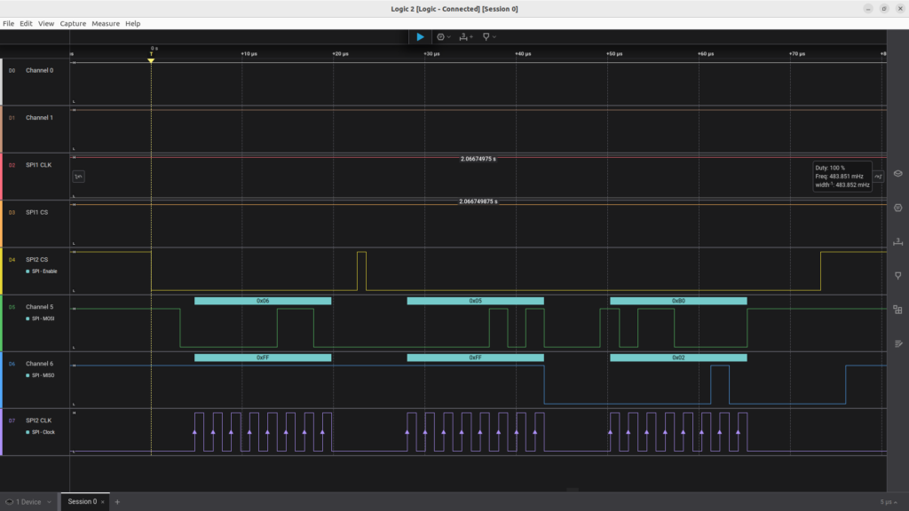
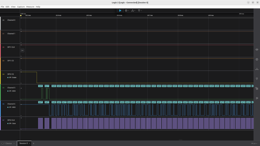
Logic Analyzer
Using the updated code which is writing and reading from memory address 0x0017, we will now take a look at the data captured by a Logic Analyzer. It displays the 4 signals used to communicate with the EEPROM and retrieve status information. We will also be able to see the commands/data being sent to the EEPROM and what is sent back to the MCU.
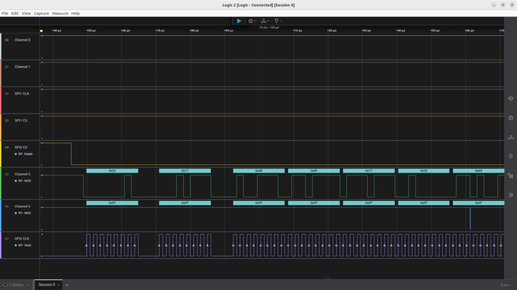
In the first screenshot below, we see 4 rows that are capturing data.
- D4 or Channel 4 – Chip Select. This signal is driven by PB6. This enables the EEPROM to be written to or read from. In an SPI model, you can have multiple Slave devices that the MCU talks to. Each Slave is only active when it’s chip select line (CS) is LOW, and disabled when High.
- D5 or Channel 5 – MOSI (Master Out/Slave In) PA7. This signal send data from the MCU to the EEPROM
- D6 or Channel 6 – MISO (Master In/Slave Out) PA6. This signal sends data from the EEPROM to the MCU
- D7 or Channel 7 – CLK Connected to PA14.
If we look at the source code EEPROM_25AA40A.c, on line 85, we shall see halStatus = HAL_SPI_Transmit(hspi, (uint8_t *)&EEPROM_WREN, 1, 100);
EEPROM_WREN is a command that is sent to the EEPROM that indicates that the chip should allow writes. EEPROM_WREN has a hex value of 0x06. We can see this on Channel 5 as the first piece of data being sent to the EEPROM from the MCU.
This is followed by the line 96 halStatus = HAL_SPI_Transmit(hspi, (uint8_t *)&EEPROM_RDSR, 1, 100); sending a command value of 0x05, which is EEPROM_RDSR. This tells the EEPROM to Read Status Register and send back that information.
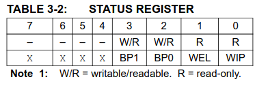
We can see that Channel 6, which is the MISO, or (Master In/Slave Out) has a value of 0x02 being sent back to the MCU. Table 3-2 below for the status register indicates a 0x02 is WEL, which means the EEPROM’s WEL (Write Enable Latch) is enabled, and will now accept data sent to it to be written.
In this next image, we can see the first byte sent out on MOSI Channel 5 has a command value of 0x02. If we look up in table 3-1 above, we can see that’s a WRITE command. This corresponds to this line in the code: 137-139 of the EEPROM_25AA40A.c source file. The next byte sent to the EEPROM has a value of 0x17, and this is the memory address to write to. If this had been an address above 0xff, such as 0x100, then bit A8 would have been include in the WRITE command, see table 3-1.
Now let’s change the output to show the same image, but instead of showing data in hexadecimal format, it will now show in ASCII. This is the same data being written to the EEPROM at address 0x17 as the above image, but just showing ASCII.
At the end of the group of bytes being written to the EEPROM, we see a 0x05 which according to table 3-1, is a RDSR command. This will tell us if the entire write has successfully been written or if the write is still in progress. if the WIP bit is non-zero, then we are still in-progress. In this case the return value is 0x03, but we are only concerned with the LSB bit 0.
In the file EEPROM_25AA40A.c source code from line 168-185, this logic handles the checking to see if the WIP bit is set to zero or still showing that the write is in-progress.
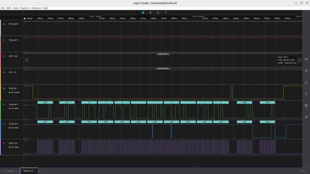
The logic keeps looping in a while loop until the RDSR command 0x05, returns a 0x00 byte value indicating that the write has comleted.
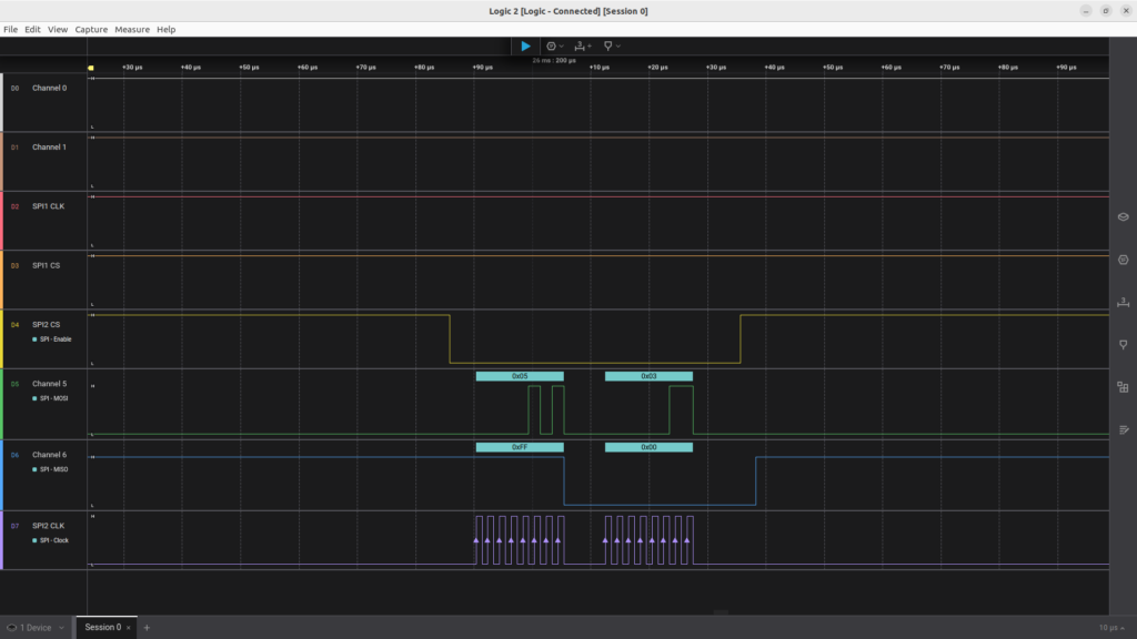
In the following screen capture we can see that we are sending another EEPROM_WREN, then EEPROM_RDSR checking the status of the WEL. Followed by the WRITE command 0x02, followed by the memory address of 0x17. We keep repeating these same sequences until all the bytes have been written. This includes checking the WIP status bit.

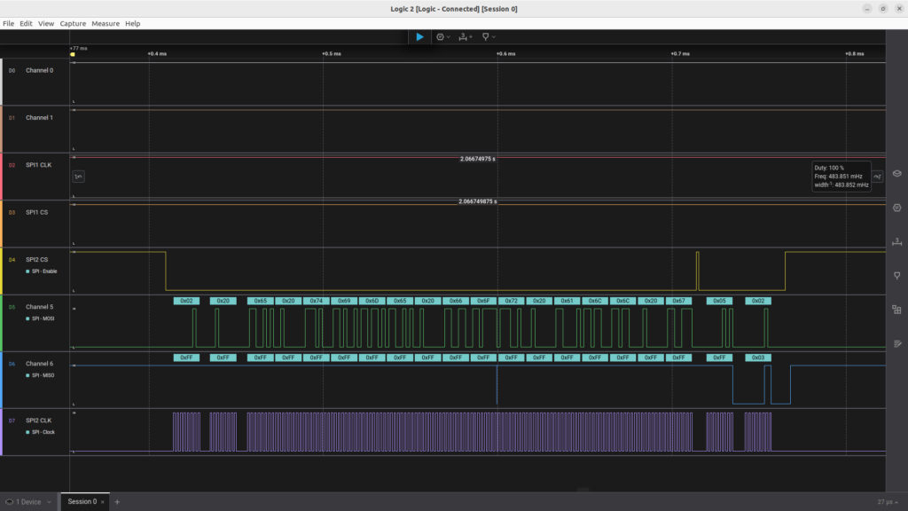
Once all the writes are completed, the testSPI_25AA40A function calls the halStatus = eepromRead(addr, (uint8_t *) &spi_buf, len); to fetch the bytes written back from the EEPROM. The first byte is a READ command 0x03 following by the memory address to read from, in this case it’s still 0x17.
The next image is the same as above, but we switch from hexadecimal output to ASCII.

If you have questions or run into trouble getting the boards programmed and talking to each other, post in the Tutorial Support forum and I will work through it with you. If project source is not linked in the tutorial, it may be available on request — use the email contact option in the site footer.